
Manuales relacionados para Nogueira NEW PECUS Duo G2


Resumen de contenidos para Nogueira NEW PECUS Duo G2
- Página 1 NEW PECUS Duo COSECHADORA DE FORRAJE FORAGE HARVESTER M A N U A L INSTRUCTIONS MANUAL DE INSTRUCCIONES ENGLISH ESPAÑOL...
- Página 3 NEW PECUS Duo COSECHADORA DE FORRAJE...
- Página 5 1. Identificación Manual de Instrucciones Cosechadora de Forraje NEW PECUS Duo G2 Español NEW PECUS Duo G2 (PLATAFORMA 736 mm) NEW PECUS Duo G2 Manual de Instrucciones...
-
Página 6: Identificación
1. Identificación 1.- IDENTIFICACIÓN Su máquina se identifica con un número de serie anotado en la etiqueta existente en la misma. Etiqueta de identificación Anote el número de serie aquí: Al enviar comunicaciones, solicitar piezas de repuesto o ayuda de la Asistencia Técnica, siempre mencione el número de serie y el modelo de su máquina. - Página 7 Todas las informaciones y especificaciones contenidas en este manual están actualizadas en el momento de su publicación. Nogueira se reserva el derecho de actualizarlos en cualquier momento, sin previo aviso. La reproducción de este manual no está permitida sin la previa autorización por escrito de Nogueira...
-
Página 8: Tabla De Contenido
Índice CONTENIDO 1.- IDENTIFICACIÓN ....................6 2.- SEGURIDAD ..................... 10 2.1- Seguridad general ....................11 2.2- Seguridad en la preparación ..................11 2.3- Seguridad en la operación ..................12 2.4- Seguridad en el mantenimiento ................13 2.5- Seguridad en la utilización del sistema hidráulico ...........14 2.6- Seguridad en el transporte ..................15 2.7- Seguridad personal ....................16 2.8- CALLEJÓNES ......................17... - Página 9 Índice 4.11.1- Colocación del Rompedor de Granos............72 4.12- Transporte ......................74 5.- OPERACIÓN ..................... 75 5.1- Recomendaciones importantes ................76 5.2- Prueba preventiva ....................76 5.3- Antes de iniciar el trabajo ..................77 5.4- Inicio de la operación ....................77 5.5- Velocidad de desplazamiento del tractor ..............78 5.6- Rotación en la toma de fuerza ................78 5.7- Apagado de la máquina ..................78 5.8- Desconectando las mangueras del tractor .............79...
-
Página 10: Seguridad
él se indican las buenas prácticas de seguridad que deben respetarse durante las etapas de utilización. En caso de cualquier duda, consulte con nosotros: Departamento de Post Ventas Nogueira: tel +55 19 3813 9226. E-mail: assistencia@nogueira.com.br Recordamos que la preservación de la salud y la integridad física de las personas debe venir siempre en primer lugar. -
Página 11: Seguridad General
2. Seguridad 2.1- Seguridad general ƒ Lea el manual de instrucciones antes de conectar la máquina. Manténgase atento y respete todas las recomendaciones de uso y seguridad durante la operación. Repase la información para los demás usuarios y mantenga el Manual en un lugar accesible a todos los usuarios y personal de mantenimiento. -
Página 12: Seguridad En La Operación
2. Seguridad 2.3- Seguridad en la operación ƒ Para la operación de esta máquina, así como para toda tarea de mantenimiento o reparación, seguir las instrucciones indicadas en el presente manual. Se debe prestar especial atención a las recomendaciones y advertencias de seguridad, además de cumplir con todas las normativas de higiene y seguridad en el trabajo que estén vigentes y sean aplicables localmente. -
Página 13: Seguridad En El Mantenimiento
2. Seguridad 2.4- Seguridad en el mantenimiento ƒ Las actividades de mantenimiento, inspección, reparación y demás intervenciones en la máquina deben ser realizadas por trabajadores habilitados, calificados, capacitados o autorizados para este fin (ítem 12.135 de la NR 12), conforme a las instrucciones de este manual, consciente de los riesgos involucrados. -
Página 14: Seguridad En La Utilización Del Sistema Hidráulico
2. Seguridad 2.5- Seguridad en la utilización del sistema hidráulico ƒ Asegúrese de que todos los componentes del sistema hidráulico se mantienen en buen estado. ƒ Reemplace inmediatamente las mangueras dañadas, cortadas, aplastadas. ƒ Siempre alivie la presión del sistema antes de desconectar una manguera hidráulica. -
Página 15: Seguridad En El Transporte
2. Seguridad 2.6- Seguridad en el transporte ƒ El transporte de la máquina acoplada al tractor no debe realizarse en vías públicas y carreteras. Esta práctica debe limitarse dentro de las propiedades y zonas rurales. Consulte al órgano de tránsito sobre las reglas y leyes vigentes en su región en cuanto a la posibilidad o no de transportar la máquina con el tractor en ciertos tramos de carreteras. -
Página 16: Seguridad Personal
2. Seguridad 2.7- Seguridad personal ƒ La seguridad del operador y demás personas es una de las principales preocupaciones en la concepción y el desarrollo de una máquina. Sin embargo, todos los años se producen muchos accidentes que podrían haberse evitado en general debido a la falta de atención y observación de las reglas de seguridad durante la operación. -
Página 17: Callejónes
(marcha atrás). con las manos. Si es necesaria la alimentación manual, use una de las máquinas de ensilaje de la línea estacionaria de Nogueira, como la EN-6800. ¡ES PROHIBIDO ALIMENTAR MANUALMENTE LA COSECHADORA! Es de exclusiva responsabilidad del productor (cliente) la planificación de la plantación para... -
Página 18: Uso De Epi
2. Seguridad 2.9- Uso de EPI Equipo de Protección Individual (EPI) es todo dispositivo de uso individual destinado a proteger la salud y la integridad física del trabajador con el fin de minimizar los riesgos del ambiente de trabajo y promover la salud, el bienestar y evitar los accidentes y enfermedades ocupacionales , conforme a la Norma Reguladora nº... -
Página 19: Adhesivos De Seguridad
2. Seguridad 2.10- Adhesivos de seguridad Los adhesivos de seguridad fijados en la máquina advierte sobre riesgos residuales y advierte para procedimientos a ser adoptados durante las fases de utilización de la misma. ƒ Mantener todos los adhesivos de seguridad visibles y en perfecto estado de conservación;... - Página 20 2. Seguridad No utilice el cardán sin las protecciones de seguridad. No suba en el cardan. No abra la cubierta de la máquina funcionando. Mantenga las manos lejos del rotor en movimiento. Prohibido permanecer sobre cualquier parte de la máquina durante la operación o el transporte. Prohibido alimentar manualmente la máquina.
-
Página 21: Medidas De Seguridad Adoptadas En El Proyecto
2. Seguridad 2.11- Medidas de seguridad adoptadas en el proyecto En el desarrollo del proyecto, se han adoptado protecciones fijas de seguridad en las zonas de operación que presentan peligro. Todas las protecciones están completamente blindadas para impedir el acceso a los puntos que ofrecen riesgo. -
Página 22: B - Protecciones De Seguridad Para Las Puntas Del Eje De Las Cajas De Transmisión
2. Seguridad B - Protecciones de seguridad C - Carenado de la plataforma: para las puntas del eje de las Además de los rodillos de alimentación cajas de transmisión: y los discos de corte, el carenado está Desarrolladas para impedir el contacto diseñado para dificultar el acceso de con las puntas de eje en movimiento. -
Página 23: Riesgos Existentes Y Acciones Necesarias
2. Seguridad 2.12- Riesgos existentes y acciones necesarias Incluso con el uso de recursos apropiados y protecciones de seguridad incorporadas, algunos riesgos residuales permanecen durante el uso de esta máquina. Esto ocurre debido a algunos componentes funcionales como los rodillos alimentadores y los discos de corte necesitan estar parcialmente expuestos para la correcta operación de la máquina. - Página 24 2. Seguridad Nunca subirse a la máquina en funcionamiento. Riesgo de caída con lesiones en la columna, cabeza y miembros. Riesgo de muerte si la caída ocurre en el área de alimentación (rollos). CÓMO ELIMINAR EL RIESGO: Nunca suba a la máquina funcionando, ya sea en el transporte o durante la operación.
- Página 25 2. Seguridad Nunca permanezca entre la máquina y el tractor durante el acoplamiento. Riesgo de impacto y/o aplastamiento de miembros si ocurre algún movimiento involuntario de la máquina o del tractor durante el acoplamiento. CÓMO ELIMINAR EL RIESGO: Elija un lugar plano para realizar el acoplamiento al tractor, esto evita que la máquina o tractor puedan moverse.
- Página 26 2. Seguridad No intente afilar las cuchillas del rotor sin protección adecuada para los ojos. Las chispas que se desprenden de las cuchillas durante el afilado pueden alcanzar directamente los ojos, causando lesiones graves. CÓMO ELIMINAR EL RIESGO: Nunca intente afilar las cuchillas sin proteger los ojos.
-
Página 27: Presentación
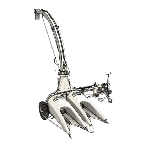
3. Presentación 3.- PRESENTACIÓN 1 Cilindro Hidráulico Mueve el quiebra-chorro. 2 Quiebra-chorro Dirige el chorro de producto picado. 3 Motor hidraulico Gira el tubo de salida. 4 Tubo de Salida. Descarga el producto picado. 5 Carenados * Mamparos del área de alimentación. 6 Rotor Pica y lanza el forraje por el tubo de salida. - Página 28 3. Presentación 14 Caja de transmisión Transmite rotación y potencia. 15 Caja de transmisión del Transmite potencia y rotor rotación. Transmite potencia y 16 Cardán rotación. 17 Pie de Apoyo Apoyo para aparcamiento. Punto de 18 Enganche enganche para carreta o vagón.
-
Página 29: Uso Previsto
3. Presentación 3.1- Uso previsto Esta máquina ha sido desarrollada para cosechar con precisión y picar cultivos forrajeros plantados en surco, como maíz, sorgo, caña, pasto y similares, produciendo forraje de excelente calidad para ensilaje y manejo diario de animales. Simultáneamente cosecha dos surcos plantados con un espaciado específico, de acuerdo con la apertura de la plataforma comprada. -
Página 30: Funcionamiento
3. Presentación Versiones disponibles: Con plataformas independientes, en las aperturas a continuación: 3.3- Funcionamiento COSECHA La cosechadora se acopla al tractor a través del sistema hidráulico de tres puntos y se acciona mediante la toma de fuerza. A medida que la máquina avanza por la plantación, las cuchillas de los rodillos de recogida cortan simultáneamente las plantas de los dos surcos. -
Página 31: Itens Que Acompañan A La Máquina
3. Presentación 3.5- Itens que acompañan a la máquina ITEM CÓDIGO DESCRIPCIÓN CANT 02.093645 Caja de Ferramientas 03.048642 Engranaje de corte de 3 mm 02.048652 Engranaje de corte de 5 mm 03.048682 Engranaje de corte de 14 mm 03.048692 Engranaje de corte 18 mm 02.045001 Perno Fusible 02.700182... -
Página 32: Itens Que Acompañan A La Máquina
3. Presentación 3.6- Itens que acompañan a la máquina ITEM CANT. CÓDIGO DESCRIPCION DEL PRODUCTO Tornillo hexagonal 9,53 x 19,05 (3/8 "x 3/4") 16UNC G5 ZB 05.000290 Tornillo hexagonal 11.11 x 38.10 (7/16 "x 1 1/2") 14UNC G5 ZB 05.000451 Arandela Plana 9,53 (3/8 ") 994 ZB 02.051162 Arandela Plana 11,11 (7/16") 994 ZB... -
Página 33: Preparación
4. Preparación 4.- PREPARACIÓN 4.1- Recepción Movimiento de la máquina embalada Para descargar o mover la máquina empacada, se debe utilizar siempre una carretilla elevadora. No hilar la máquina empaquetada utilizando el cabrestante, la grúa, etc. La máquina se empaqueta cuando está destinada a la exportación. -
Página 34: Montajes
4. Preparación 4.2- Montajes Con el objetivo de ganar espacio y facilitar el transporte, algunos componentes se suministran desmontados de la máquina. Observe las siguientes instrucciones para proceder a la instalación de estos elementos. 4.2.1- Montaje de la rueda de apoyo La rueda de apoyo sale de la fábrica desmontada de la máquina. -
Página 35: 2- Montaje De Los Limitadores De Apertura
4. Preparación 4.2.2- Montaje de los limitadores de apertura Los limitadores (A) y (D) se usan exclusivamente para cosechar maíz y sorgo y deben eliminarse cuando se cosechan otros productos como pasto y caña. Monte los limitadores (A) y (D) en los alineadores (B). - Página 36 4. Preparación Coloque el desviador (E) sobre el alineador (F); Fijelos con 1 tornillo (H) y 2 tornillos (J); H= Tornillo de cabeza hexagonal de 7/16" x 1" (01 pieza) J= Tornillo hexagonal 7/16"x 1.1/2" (02 piezas) J= Tuerca hexagonal autoblocante 7/16" (02 piezas) J= Arandela plana 7/16"...
-
Página 37: 4- Montaje Del Rodillo Tumbador
4. Preparación 4.2.4- Montaje del rodillo tumbador: Primero ajuste el sujetador (J) al soporte (K); Coloque el soporte (K) en los dos agujeros en la caja como se muestra en la ilustración. Monte el fijador (L) con el tornillo y la arandela (M);... -
Página 38: 5- Montaje Del Deflector
4. Preparación 4.2.5- Montaje del deflector Coloque los 2 soportes (J) en el deflector (K), como se muestra en la figura del lateral; Asegure los soportes (J) al deflector (K) con las arandelas y tuercas (L); L= Tuerca hexagonal autoblocante M12 (02 piezas) Arandela Plana M12 (02) Monte el deflector (K) como se muestra... -
Página 39: 6- Montaje De Carenado (Solo Plataformas 800 / 900 Y 950 Mm)
4. Preparación 4.2.6- Montaje de carenado (solo plataformas 800 / 900 y 950 mm) Coloque el carenado (S) sobre los alineadores de la máquina; Coloque el espaciador (T) en el carenado (S) suministrado con la máquina; Fije el carenado con el tornillo, las arandelas y tuerca hexagonal (U) suministradas con la máquina;... -
Página 40: 7- Ajuste De Los Limitadores De Apertura
4. Preparación 4.2.7- Ajuste de los limitadores de apertura La función de los limitadores (A) y (B) es ajustar la apertura de la alimentación con el objetivo de obtener el máximo uso de las mazorcas (maíz) y los racimos (sorgo). Los limitadores deben usarse en las cosechas de maíz y sorgo y reservarse para cosechar caña de azúcar, pasto y otros. -
Página 41: 8- Montaje De Tumbadores Y Desviadores (Solo Plataforma De 736 Mm)
4. Preparación 4.2.8- Montaje de tumbadores y desviadores (solo plataforma de 736 mm) ¡ADVERTENCIA! Apague el motor del tractor y retire la llave de arranque antes de comenzar el procedimiento siguiente. Coloque el desviador (E) superponiendo el alineador (F); Fijelos con 1 tornillo (H) y 2 tornillos (J); H= Tornillo hexagonal de 7/16"... - Página 42 4. Preparación Monte el tumbador (K) en la caja del rodillo, fijándolo con los 2 tornillos y arandelas (L); L= Tornillo hexagonal de 3/8" x 1" (02) L= Arandela plana de 3/8" (02) Coloque el tornillo y la arandela (M); M= Tornillo de cabeza hexagonal de 7/16"...
-
Página 43: 9- Montaje Del Tubo De Salida
4. Preparación 4.2.9- Montaje del tubo de salida Para facilitar su transporte, el tubo de salida se suministra parcialmente desmontado. Observe las instrucciones que siguen para proceder con su montaje. COMPONENTES DEL TUBO DE SALIDA: Monte el doble quiebra-chorro (A) en el segmento de la boquilla (B). - Página 44 4. Preparación Monte el segmento (D) en el segmento (E). Fijalo con los ocho tornillos, arandelas y tuercas (T); T= Tornillo de Cabeza Redonda y Cuelo Cuadrado M10 x 30 mm (08) T= Arandela plana M10 (08) T= Tuerca hexagonal autoblocante M10 (08) Monte el segmento (D) en el segmento (E).
- Página 45 4. Preparación Asegure la manguera en los 4 puntos del tubo de salida, utilizando los sujetadores (L), las tuercas y las arandelas (M); M= Arandela plana M8 (08) M= Tuerca hexagonal autoblocante M8 (08) Monte los dos tensores (T), fijándolos en el tubo de salida con los tornillos, arandelas y tuercas (S);...
- Página 46 4. Preparación Asegure el tensor del tubo de salida con el pasador (K). Bloquee con las dos pasadores abatibles (L). Si es necesario, afloje la contratuerca (G) y ajuste la longitud del tensor (H). Apriete el tensor girando el eje (H). Vuelva a apretar la contratuerca (G);...
-
Página 47: 10- Poner La Cosechadora En Posición Lateral
4. Preparación 4.2.10- Poner la cosechadora en posición lateral Para facilitar el transporte, la cosechadora sale de la fábrica preparada para el acoplamiento en la posición trasera del tractor (con el brazo doblado). Esta es la posición ideal para hacer callejones y transportar la máquina. Observe las instrucciones que siguen para colocarlo en la posición de recolección (lateral). - Página 48 4. Preparación Coloque el pasador (F), el pasador aleta (G), apriete el tensor (E) y la contratuerca (J). Repita el procedimiento en el otro tensor; Retire el pasador (K); Mueva la caja de transmisión (L) hacia un lado; Asegure la caja en esta posición con el tornillo y la tuerca (M);...
-
Página 49: 11- Poner La Cosechadora En Posición Inversa (Apertura De Callejones)
4. Preparación 4.2.11- Poner la cosechadora en posición inversa (apertura de callejones) La cosechadora puede cosechar tanto en la posición lateral como en la trasera (ideal para abrir callejones). Para colocarlo en la posición trasera, observe las siguientes instrucciones: ACOPLE LATERAL ACOPLE TRASERO Retire el cardán (N). - Página 50 4. Preparación Asegure la caja de cambios en esa posición, colocando el pasador y el pasador aleta (K); Suelte el tensor (B); Afloje la contratuerca (J), el tensor (E) y retire el pasador (G) y el pasador (F). Repita el procedimiento en ambos tensores (E); Manual de Instrucciones...
- Página 51 4. Preparación La figura del lado muestra el brazo de acoplamiento en la posición trasera; Asegure el brazo (D) en esa posición usando el tensor (B). Coloque el pasador y el pasador aleta (C); Apriete el tensor (B) y la contratuerca (A). Manual de Instrucciones...
-
Página 52: 12- Poner El Tubo De Salida En La Posición De Transporte
4. Preparación 4.2.12- Poner el tubo de salida en la posición de transporte Al transportar la cosechadora conectada al tractor, es importante colocar la máquina en la posición 'trasera' y bajar el tubo de salida. Este procedimiento evita daños y accidentes en caso de contacto con árboles, la red eléctrica, etc. Para colocarlo en la posición trasera, consulte el item: 'COLOCACIÓN DE LA COSECHA EN LA POSICIÓN TRASERA', para bajar el tubo de salida, proceda de la siguiente manera:... -
Página 53: 13- Poner Tubo De Salida En Posición De Trabajo
4. Preparación 4.2.13- Poner tubo de salida en posición de trabajo Retire los pasadores aleta (G) y suelte los dos brazos (F); Asegure los brazos (F) al pasador aleta del tubo de salida (E); Coloque los dos pasadores aleta en el pasador (E);... -
Página 54: Acoplamiento Al Tractor
4. Preparación 4.3- Acoplamiento al tractor La cosechadora puede trabajar en las posiciones lateral o trasera del tractor. El acoplamiento se lleva a cabo de la misma manera, es decir, utilizando los tres puntos de elevación hidráulicos del tractor. Durante el acoplamiento: ƒ... -
Página 55: Acoplamiento
4. Preparación Acoplamiento: Aproxime el tractor de la máquina, procurando alinear la toma de fuerza del tractor con el eje de la máquina; Inicie la acogida por el brazo izquierdo (A), luego el derecho (B) y finalmente el brazo de articulación de tres puntos (C); Cierre los brazos con los pernos de bloqueo suministrados con la máquina;... -
Página 56: No Seguir Estas Instrucciones Puede Conducir A Accidentes Con Daños
4. Preparación Levante y traba el pie de apoyo (P). El brazo de acoplamiento de la cosechadora permite el acoplamiento en diferentes puntos. Use la posición que mejor se adapte a su tractor. Después del acoplamiento, compruebe que hay suficiente espacio entre el neumático trasero del tractor y la máquina (fig. -
Página 57: Nivelación
4. Preparación 4.4- Nivelación Transversal ƒ Elevar la máquina a aproximadamente 20 cm del suelo. ƒ Recoger el pie de apoyo (A). ƒ Mirando la máquina hacia trasera, asegúrese de que esté nivelada. ƒ Baje la máquina y haga los ajustes necesarios para que quede nivelada. -
Página 58: Cardan De La Toma De Fuerza
4. Preparación 4.5- Cardan de la toma de fuerza 4.5.1- Longitud del cardan Dependiendo del tractor utilizado, puede ser necesario adecuar la longitud del cardan. Haga la verificación y, si es necesario, corte el cardan, procediendo como se describe a continuación (vea las instrucciones para el corte en el manual del cardan). -
Página 59: 2- Cómo Acoplar El Cardan
4. Preparación TRACTOR MÁQUINA Recomendaciones: ƒ Los pedazos cortados de la barra, del tubo y de la protección plástica del cardan deben tener la misma longitud. ƒ Utilizando una lima, darle acabado en las partes cortadas. A continuación, lubrique con una fina capa de grasa. ƒ... - Página 60 4. Preparación ƒ Después de la colocación del cardan, prenda las cadenas de forma que permitan la articulación en cualquier condición de trabajo y de transporte. ƒ Compruebe la longitud del cardan siempre que utilice un modelo diferente de tractor. ƒ...
-
Página 61: Conexión Hidráulica
4. Preparación 4.6- Conexión hidráulica Conectando las mangueras al tractor: ¡ADVERTENCIA! Antes de conectar y desconectar las mangueras es necesario aliviar la presión del circuito hidráulico. Para esto, apague el tractor y accione algunas veces las palancas hasta aliviar la presión. Con las palancas del control en la posición neutra, tire de las mangueras rápidamente: la desconexión ocurrirá... -
Página 62: Tubo De Salida Hidráulico
4. Preparación 4.7- Tubo de salida hidráulico La cosechadora viene equipada de fábrica con tubo de salida de accionamiento hidráulico. La dirección del quiebra chorro y los movimientos para subir / bajar el tubo de salida se realizan mediante cilindros hidráulicos. El movimiento de giro es realizado por un motor hidráulico. -
Página 63: 1- Joystick
4. Preparación 4.7.1- Joystick El JOYSTICK es un control remoto que permite al operador, desde el tractor, girar el tubo de salida y mover el quiebra chorro, dirigiendo el chorro de producto picado. JOYSTICK 4.7.2- Montaje de joystick en el tractor El Joystick debe montarse en la palanca de control hidráulico del tractor, ya que se... -
Página 64: 3- Conexiones De Joystick
4. Preparación 4.7.3- Conexiones de joystick Conecte los terminales del cable del Joystick a la válvula solenoide de la cosechadora (figura al lado). A continuación, conecte los cables positivo y negativo del Joystick a los polos correspondientes de la batería del tractor (12v). -
Página 65: 4- Girando El Tubo De Salida
4. Preparación 4.7.4- Girando el tubo de salida El movimiento de giro del tubo de salida se realiza mediante un sinfin helicoidal, accionado por un motor hidráulico. Esta característica le permite colocar el tubo de salida para la descarga en la dirección deseada. -
Página 66: Ajuste De Los Tumbadores (Solo Plataforma De 736 Mm)
4. Preparación 4.8- Ajuste de los tumbadores (solo plataforma de 736 mm) Los tumbadores (T) tienen la función de inclinar las plantas, con el objetivo de facilitar la recolección y proporcionar el máximo uso en la cosecha. Los tumbadores se pueden empotrar o avanzar de acuerdo con las características del producto: cuanto más altas son las plantas, más avanzado debe poner el tumbador y... -
Página 67: Tamaños De Corte
4. Preparación 4.9- Tamaños de corte Se pueden obtener diferentes tamaños de corte, que se cambian de acuerdo con los engranajes utilizados y el número de cuchillas del rotor del picador. Los tamaños posibles van desde 2 hasta un máximo de 36 mm. La siguiente tabla muestra los posibles tamaños de picado, sus pares de engranajes y la cantidad de cuchillas necesarias para... -
Página 68: Cantidad De Cuchillas Del Rotor
4. Preparación ¡NOTA! ¿Qué tamaños de corte usar? Si no tiene experiencia previa en la propiedad que pueda ayudarlo a determinar el tamaño de pozo ideal para sus condiciones de trabajo, busque siempre el consejo de técnicos expertos en alimentación animal. 4.10- Cantidad de cuchillas del rotor Los rotores picadores de la cosechadora están dimensionados para trabajar con 12, 6, 4 o 3... -
Página 69: 1- Cómo Cambiar La Cantidad De Cuchillas Del Rotor
4. Preparación 4.10.1- Cómo cambiar la cantidad de cuchillas del rotor La máquina sale de la fábrica preparada para cosechar con 12 cuchillas en cada rotor. Si desea cosechar con 7 cuchillas, debe prestar atención a la posición correcta cuando retire las cuchillas, de acuerdo con las instrucciones a continuación. - Página 70 4. Preparación Para cambiar la cantidad de cuchillas del rotor: ¡ADVERTENCIA! Apague el motor del tractor y retire la llave de arranque antes de comenzar el procedimiento siguiente. ¡ADVERTENCIA! Es obligatorio el uso de EPI (Equipo de Protección Individual) durante la operación, mantenimiento y regulaciones de la máquina.
- Página 71 4. Preparación Retire el tubo de salida (G); Retire los 12 tornillos que aseguran las dos cubiertas (H) a la máquina; Retire las cubiertas (H) de los rotores; Retire los tornillos que aseguran la cuchilla al rotor (J). Quite la cuchilla y el soporte. Mantenga la misma cantidad de cuchillas en ambos rotores.
-
Página 72: Sistema 'Rompedor De Granos
4. Preparación 4.11- Sistema 'ROMPEDOR DE GRANOS' FONDO El sistema 'Rompedor de Granos' fue ROMPEDOR LISO desarrollado para auxiliar en la rotura de DE GRANOS granos de forrajeras como maíz y sorgo, para favorecer el aprovechamiento (digestibilidad) del grano por los animales. Los trabajos de investigación evaluando el corte y procesamiento de granos en silajes de maíz mostraron adecuado patrón en el tamaño... - Página 73 4. Preparación ¡NOTA! Una manera práctica para montar el rompedor de granos (o el fondo liso) en la máquina es colocarlo sobre el rotor y, con las manos, girar los dos juntos (rotor y rompedor de granos) haciendo el rompedor de granos entrar en la carcasa.
-
Página 74: Transporte
4. Preparación 4.12- Transporte Siempre que sea necesario transportar la máquina a largas distancias o utilizando vías públicas, el transporte se realizará por camión, carreta u otro vehículo similar. ¡ADVERTENCIA! La máquina debe estar completamente en el interior de la carrocería del vehículo utilizado para el transporte. -
Página 75: Operación
5. Operación 5.- OPERACIÓN Los trabajos con la máquina deben ser realizados únicamente por profesionales habilitados, calificados, capacitados o autorizados para este fin. El uso sin el conocimiento necesario puede resultar en un funcionamiento incorrecto con riesgo de accidentes graves. La atención al utilizar la máquina garantiza la seguridad a usted y a otras personas. -
Página 76: Recomendaciones Importantes
5. Operación 5.1- Recomendaciones importantes ƒ Se recomienda trabajar con una altura de corte que la máquina no recoja tierra, perjudicial tanto para la máquina y para el forraje. ƒ El ángulo máximo de inclinación del cardan en el trabajo no puede sobrepasar . -
Página 77: Antes De Iniciar El Trabajo
5. Operación 5.3- Antes de iniciar el trabajo Compruebe con atención: ƒ Si las cuchillas del rotor están afilados; ƒ Si la máquina está lubricada; ƒ Si la máquina está regulada para el corte deseado; ƒ Si el cardan está debidamente trabado en los ejes de la máquina y en la toma de fuerza del tractor;... -
Página 78: Velocidad De Desplazamiento Del Tractor
5. Operación 5.5- Velocidad de desplazamiento del tractor La velocidad de desplazamiento del tractor es un factor que influye directamente en la producción de la máquina y en la calidad del corte. Seleccione la marcha que proporcione la velocidad adecuada considerando las condiciones de cosecha, tales como: tipo de cultivo, porte de las plantas, inclinación del terreno, potencia del tractor utilizado, etc. -
Página 79: Desconectando Las Mangueras Del Tractor
5. Operación 5.8- Desconectando las mangueras del tractor Antes de conectar y desconectar las mangueras es necesario aliviar la presión del circuito hidráulico. Para esto, apague el tractor y accione algunas veces las palancas hasta aliviar la presión. Con las palancas del mando a distancia del tractor en posición neutra, tire de las mangueras rápidamente: la desconexión se producirá... -
Página 80: Obstrucción (Atascamiento)
5. Operación 5.10- Obstrucción (atascamiento) En caso de obstrucción, retire el material acumulado dentro de la máquina utilizando la llave de inversión provista con el mismo. ¡PELIGRO! LLAVE DE INVERSIÓN En el caso atascamiento de la máquina, apague inmediatamente el tractor y retire la llave del motor de arranque. - Página 81 5. Operación Retire el tornillo (E) de la tapa protectora; Levante la tapa protectora (F); Coloque la llave de inversión (G) en el extremo del eje de la caja de engranajes. Con las manos, gire la llave de inversión en la dirección que se muestra en la ilustración.
-
Página 82: Mantenimiento
6. Mantenimiento 6.- MANTENIMIENTO El mantenimiento periódico, realizado de forma adecuada, es la manera más eficaz de garantizar máxima eficiencia y durabilidad para su máquina. ¡NOTA! Conforme a la Norma Reguladora NR- 12, las intervenciones en la máquina deben ser realizadas por profesionales habilitados, calificados, capacitados o autorizados para este fin. -
Página 83: Recomendaciones Generales
6. Mantenimiento 6.1- Recomendaciones generales ƒ Nunca funcione la máquina por períodos prolongados dentro de recintos cerrados y sin ventilación, el monóxido de carbono expelido por los gases de escape del tractor es altamente tóxico. ƒ Mantenga el área de mantenimiento limpia. Pisos mojados o aceitosos son resbaladizos y peligrosos. -
Página 84: Tabla De Mantenimiento
6. Mantenimiento 6.2- Tabla de mantenimiento INTERVALO LEYENDA (horas trabajadas) inspeccionar Lubricar cambiar apretar afilar realizar ACCIONES NECESARIAS Operador Protecciones de seguridad autorizado Operador Tornillos y tuercas de fijación en general. autorizado Operador ... - Página 85 6. Mantenimiento INTERVALO LEYENDA (horas trabajadas) inspeccionar Lubricar cambiar apretar afilar realizar ACCIONES NECESARIAS Compruebe la holgura entre Después de cada afilado de las cuchillas Operador las cuchillas y la contra- autorizado del rotor. cuchilla del rotor.
-
Página 86: Articulando Las Plataformas
6. Mantenimiento 6.3- Articulando las plataformas Para facilitar el acceso a las contracuchillas y otras partes internas de la máquina, las plataformas (A) y (B) tienen un sistema de articulación lateral. ¡CUIDADO! Elija una ubicación plana para realizar el procedimiento de articulación de la plataforma. - Página 87 6. Mantenimiento Retire el tornillo (A) y levante el carenado (B). Use la varilla (R) para soportar el carenado abierto. Retire el desviador lateral (C); Retire la rueda (D); Retire el deflector central (E); Retire los 2 tornillos (F) y la tapa de la caja de cambio de picado (E).
- Página 88 6. Mantenimiento Levante el bloqueo (N), afloje el tornillo (O) y retire el pasador (P). Con cuidado, articule la plataforma hacia el lado (figura al lado). Repita el procedimiento anterior para articular la otra plataforma. Para devolver las plataformas a la posición de trabajo, realice el procedimiento en orden inverso.
-
Página 89: 1- Cómo Cambiar Las Cuchillas Del Rotor
6. Mantenimiento 6.3.1- Cómo cambiar las cuchillas del rotor Las cuchillas de los rotores deben reemplazarse si están dañadas o desgastadas, de modo que sea imposible afilarlas y ajustarlas con las contracuchillas. ¡ADVERTENCIA! Apague el motor del tractor y retire la llave de arranque antes de comenzar el procedimiento siguiente. - Página 90 6. Mantenimiento Retire el tornillo (A) y levante el carenado (B). Use la varilla (C) para soportar el carenado abierto. Repita el procedimiento y abra el otro carenado (D); En este ejemplo, cambiaremos las cuchillas del rotor derecho (lado de la rueda), recordando que el procedimiento es el mismo para ambos rotores;...
- Página 91 6. Mantenimiento ¡IMPORTANTE! Después de la sustitución de las cuchillas del rotor, regule las cuchillas con la contracuchilla (consulte el ítem 6.7 - 'CÓMO REGULAR LAS CUCHILLAS CON LA CONTRACUCHILLA DEL ROTOR') ¡ATENCIÓN! Después del montaje de las cuchillas en el disco del rotor, compruebe el apriete de todos los tornillos de fijación con máxima atención.
-
Página 92: Cómo Invertir O Cambiar Las Contracuchillas De Los Rotores
6. Mantenimiento 6.4- Cómo invertir o cambiar las contracuchillas de los rotores Revise la contracuchilla cada vez que afile las cuchillas del rotor. Si la dificultad de corte persiste después del afilado, es probable que la contracuchilla esté muy desgastada, dañada o no esté... - Página 93 6. Mantenimiento Ajuste las contracuchillas con las cuchillas del rotor (vea el ítem 6.7). Ensamble el rascador (D) y ajuste los 3 tornillos (A), sin apretarlos. TIRE DEL RASCADOR TOTALMENTE HACIA ADELANTE. Mantenga los tornillos (A) flojos. Vuelva la plataforma de alimentación a la posición de trabajo.
-
Página 94: Cómo Ajustar O Reemplazar Los Rascadores De Rodillos Planos
6. Mantenimiento 6.5- Cómo ajustar o reemplazar los rascadores de rodillos planos La función del rascador (D) es evitar que el material cosechado se enrolle en el rodillo liso (B) o se acumule dentro de la caja, obstruyendo la alimentación del recolector. Para que el rascador sea eficiente, el espacio entre el rascador y el rodillo liso no puede ser mayor de 0,5 mm. -
Página 95: Sincronizando Los Rotores
6. Mantenimiento 6.6- Sincronizando los rotores La cosechadora sale de la fábrica con los dos rotores sincronizados, de modo que las cuchillas de uno no cortan al mismo tiempo que las cuchillas del otro. Mantener esta regulación es muy importante, ya que de esta forma la cosechadora requerirá... -
Página 96: Cómo Regular Las Cuchillas Con La Contracuchilla Del Rotor
6. Mantenimiento 6.7- Cómo regular las cuchillas con la contracuchilla del rotor El ajuste correcto de las cuchillas con la contracuchilla asegura una mayor eficiencia operativa, mejor calidad de corte, menos potencia del tractor y menor consumo de combustible. Mantenga una holgura máxima de 0,5 mm entre la cuchilla y la contracuchilla para el mejor rendimiento de la máquina. - Página 97 6. Mantenimiento Vuelva la plataforma de alimentación a la posición de trabajo. Al volverla, el rascador se desplazará hasta la posición de trabajo correcta. Abra la plataforma nuevamente y apriete los 3 tornillos (A). ¡ADVERTENCIA! Después de la regulación, gire manualmente el rotor dando una vuelta completa.
-
Página 98: Afilado De Las Cuchillas Del Rotor
6. Mantenimiento 6.8- Afilado de las cuchillas del rotor El afilador incorporado en la cosechadora permite afilar todos las cuchillas simultáneamente, en el AFILADOR lugar de la cosecha. AFILADOR Las cuchillas afiladas consumen menos energía del tractor para picar las plantas, reducen el consumo de combustible y garantizan la mejor calidad de corte. -
Página 99: Cómo Afilar Las Cuchillas
6. Mantenimiento 6.8.2- CÓMO AFILAR LAS CUCHILLAS Afloje la perilla (G) y retire la cubierta (H). Conecte la toma de fuerza en rotación de trabajo (540 rpm). Con cuidado, gire la perilla (F) en sentido horario hasta que la piedra del afilador toque las cuchillas;... - Página 100 6. Mantenimiento Si las cuchillas están muy desgastadas, no posibilitando la regulación con la contracuchilla, sustituya todas (el kit completo). La sustitución unitaria de cuchillas causará el desequilibrio en el rotor. Cuando la piedra del afilador esté muy desgastada, cámbiela por otra nueva, siguiendo las instrucciones de este manual.
-
Página 101: Cómo Sustituir La Piedra Del Afilador
6. Mantenimiento 6.9- Cómo sustituir la piedra del afilador Cambie la piedra del afiador al constatar que ha perdido la capacidad de afilado. ¡ADVERTENCIA! Apague el motor del tractor y retire la llave de arranque antes de comenzar el procedimiento siguiente. Afloje la perilla (A) y retire la cubierta (B). -
Página 102: Pernos Fusibles
6. Mantenimiento 6.10- Pernos Fusibles La cosechadora está equipada con dos pernos fusible ubicados en los ejes de los engranajes de cambio de corte. La función de estos pernos es proteger la cosechadora en caso de que recoja algún cuerpo extraño (pedazos de hierro, piedra, madera, etc.) o en caso de sobrecarga durante la cosecha. - Página 103 6. Mantenimiento Retire los 2 tornillos (C) y la cubierta de la caja de engranajes (D); Retire los dos engranajes (E); Retire la caja de cambio de corte (F); Utilizando el punzón que se encuentra en la caja de herramientas de la máquina, retire el perno fusible (H) que esté...
-
Página 104: Calibración De Los Neumáticos
6. Mantenimiento 6.11- Calibración de los neumáticos La calibración del neumático determina en gran medida la vida útil del neumático. Verifique la presión con el neumático frío y, si es necesario, calíbrelo. Presión recomendada: Neumático: 60 libras / pulgada². (60 psi - 4.1 bar) (según el fabricante) BAJA CORRECTO... -
Página 105: Lubricación
6. Mantenimiento 6.12- Lubricación La lubricación adecuada y regular es indispensable para garantizar el buen rendimiento y la durabilidad de la máquina. Los intervalos indicados tienen en cuenta su utilización en condiciones normales de trabajo. En condiciones severas, los intervalos deben ser reducidos. -
Página 106: 1- Lubricación Con Grasa
6. Mantenimiento 6.12.1- Lubricación con grasa Antes de lubricar, limpie bien los engrasadores para evitar la contaminación de la grasa. Sustituir los engrasadores dañados. La lubricación es más eficiente cuando se realiza al final del período de trabajo, ya que la grasa fluye mejor mientras la máquina está... -
Página 107: Tubo De Salida
6. Mantenimiento AFILADORES Lubrique a través de los engrasadores los dos afiladores cada 8 horas de trabajo o diariamente. TUBO DE SALIDA Lubrique a través de los seis engrasadores cada 8 horas de trabajo o diariamente. SIN FIN DEL TUBO DE SALIDA Lubrique a través de las dos graseras cada 8 horas de trabajo o diariamente. -
Página 108: Engranajes De Caja De Rodillos
6. Mantenimiento ENGRANAJES DE CAJA DE RODILLOS Utilizando una engrasadora o una bomba lubricar con grasa especial para rodamientos, a base de jabón de litio, clasificación NLGI 2 (Ejemplo: LUBRAX LITH-2). Lubrique los puntos indicados en el costado cada 8 horas de trabajo o diariamente. Al realizar la revisión anual de la máquina o si la caja de engranajes (C) necesita abrirse para mantenimiento, se debe organizar el... -
Página 109: 2- Lubricación Con Aceite
6. Mantenimiento 6.12.2- Lubricación con aceite 6.12.3- CAJAS DE TRANSMISIÓN (A) Y (B) ¡ADVERTENCIA! Apague el motor del tractor y retire la llave de arranque antes de comenzar el procedimiento siguiente. Aceite recomendado: 150/CLP. Viscosidad: ISO 150. Especificación: DIN 51517/3. Capacidad de aceite (A) Caja del rotor izquierdo: 1,5 litros. -
Página 110: 4- Caja De Transmisión (C)
6. Mantenimiento 6.12.4- CAJA DE TRANSMISIÓN (C) ¡ADVERTENCIA! Apague el motor del tractor y retire la llave de arranque antes de comenzar el procedimiento siguiente. Aceite recomendado: 150/CLP. Viscosidad: ISO 150. Especificación: DIN 51517/3. Capacidad de aceite (C) Caja: 2,5 litros. ABASTECIMIENTO Verificación del nivel de aceite: Limpie alrededor del tapón de nivel de la caja. -
Página 111: 5- Caja De Transmisión Tdp (D)
6. Mantenimiento 6.12.5- CAJA DE TRANSMISIÓN TDP (D) ¡ADVERTENCIA! Apague el motor del tractor y retire la llave de arranque antes de comenzar el procedimiento siguiente. Aceite recomendado: 150/CLP. Viscosidad: ISO 150. Especificación: DIN 51517/3. Capacidad de aceite (D) Caja TDF: 2,3 litros. Verificación del nivel de aceite: Limpie alrededor del tapón de nivel de la caja. - Página 112 6. Mantenimiento ACEITES RECOMENDADOS PETROBRAS LUBRAX GEAR 150 TEXACO MEROPA 150 AGIP BLASIA 150 SHELL OMALA 150 Cuidado, el aceite puede estar a una temperatura elevada. Utilice los EPI adecuados (guantes, gafas, etc). Evite el contacto directo con el aceite drenado.
-
Página 113: Conservación
6. Mantenimiento 6.13- Conservación Tan importante como el mantenimiento preventivo es la conservación diaria de la máquina. Este cuidado consiste básicamente en la limpieza y protección contra la intemperie y los efectos corrosivos de algunos productos. Siga las siguientes recomendaciones para asegurar una larga vida útil de su equipo. -
Página 114: 3- Almacenamiento
6. Mantenimiento 6.13.3- Almacenamiento En el período en que la máquina se quede sin usar, antes de guardarla, se recomienda realizar la revisión general indicada en el ítem anterior. Después de la revisión: ƒ Afloje completamente las correas y cadenas de transmisión (en los modelos donde haya). -
Página 115: Desactivación
7. Desactivación 7.- DESACTIVACIÓN Esta máquina ha sido desarrollada para ofrecer una larga vida útil, necesitando para que las recomendaciones de este manual sean observadas y seguidas. Al final de la vida útil, será necesario promover el descarte de la máquina, dando el destino adecuado a las partes que la componen. -
Página 116: Fallas Y Soluciones
8. Guía práctica 8.- FALLAS Y SOLUCIONES Se presentan a continuación los síntomas más comunes de fallas de operación, sus probables causas y las medidas que debe tomar el operador. En caso de duda, consulte a su distribuidor o póngase en contacto con nuestro departamento de asistencia técnica. - Página 117 8. Guía práctica La máquina no recoge el producto. Causa probable Solución Perno(s) de seguridad roto(s). Sustituya lo(s) perno(s) de seguridad. Tractor por debajo de la potencia Utilice un tractor con potencia indicada. mínima recomendada. Rotación de la toma de fuerza Utilice rotación de 540 rpm.
-
Página 118: Especificaciones
9. Especificaciones 9.- ESPECIFICACIONES 9.1- Caracteristicas tecnicas Potencia requerida en la TDF 80 a 120 cv Rotación en la toma de fuerza 540 rpm Rotación del rotor picador (con caja) 1539 rpm Número de cuchillas por rotor picador Número de rotores Capacidad productiva estimada* Hasta 45 ton / h 2 / 3 / 4 / 6 / 7 y 9... -
Página 119: Dimensiones (En Mm)
9. Especificaciones 9.2- Dimensiones ( en mm ENTRE LÍNEAS 736 mm 800 mm 900 mm 950 mm 4480 4480 4480 4480 3850 3880 3920 3950 2440 2440 2440 2440 2800 2800 2800 2800 1500 1460 1420 1400 4465 4465 4465 4465 2300 2300... -
Página 120: Tabla De Torque De Tornillo
9. Especificaciones 9.3- Tabla de torque de tornillo Unidad de torque: N.m Manual de Instrucciones... -
Página 121: Tabla De Medidas De Llaves
9. Especificaciones 9.4- Tabla de medidas de llaves Manual de Instrucciones... -
Página 122: Bibliografia
9. Especificaciones BIBLIOGRAFIA Normas técnicas observadas en las fases de diseño y construcción de este equipo: • Norma de Seguridad en el Trabajo en Máquinas y Equipos NR-12 • ABNT NBR ISO 121000 Manual de Instrucciones... -
Página 123: Esquema Electrico
9. Especificaciones ESQUEMA ELECTRICO Cable negro – negative Cable coloreado – positive Batería del tractor Valvula Manual de Instrucciones... -
Página 124: Esquema Hidraulico
9. Especificaciones ESQUEMA HIDRAULICO Manual de Instrucciones... -
Página 125: Certificado De Garantía
09 (nueve) últimos meses - garantía adicional concedida por Nogueira Máquinas Agrícolas. 2- Consiste en la presente garantía, en el compromiso de Nogueira en reparar o sumi- nistrar gratuitamente, en su fábrica, las piezas que a su exclusivo juicio presentan defectos de fabricación. - Página 126 Manual de Instrucciones...
- Página 127 Manual de Instrucciones...
- Página 128 Manual de Instrucciones...
- Página 129 NEW PECUS Duo FORAGE HARVESTER...
- Página 131 1. Identification Instructions Manual Forage Harvester NEW PECUS Duo G2 English NEW PECUS Duo G2 (PLATFORM 736 mm) NEW PECUS Duo G2 Instructions Manual...
- Página 132 1. Identification 10.- IDENTIFICATION Your machine is identified with a serial number noted on the tag on the machine. Identification tag Write down the serial number here: By sending messages, requesting spare parts or Technical Support, always inform the serial number and model of your machine. Instructions Manual...
- Página 133 All information and specifications in this manual are current at the time of publication. Nogueira reserves the right to update them at any time, without prior notice. Reproduction of this manual is not permitted without the prior written permission of Nogueira Máquinas Agrícolas.
- Página 134 Table of Contents Table of Contents 1.- IDENTIFICATION....................4 2.- SAFETY PRECAUTIONS ..................8 2.1- General safety ......................9 2.2- Safety in the preparation ..................9 2.3- Operational safety ....................10 2.4- Safety in maintenance ...................11 2.5- Safety in the use of the hydraulic system ..............12 2.6- Safety in transportation ..................13 2.7- Personal safety.......................14 2.8- Clearance ......................15...
- Página 135 Table of Contents 4.9- Theoretical length of cut ..................65 4.10- Number of rotor knives ..................66 4.12- Transport .......................72 5.- OPERATION ...................... 73 5.1- Important recommendations .................74 5.2- Preventive test .....................74 5.3- Before starting the operation .................75 5.4- Starting the operation ...................75 5.5- Tractor travel speed ....................76 5.6- Power take-off speed .....................76 5.7- Shutting down the machine ..................76...
-
Página 136: Safety Precautions
It indicates the good safety practices that must be respected during the steps of use. If you have any questions, please contact us: Nogueira Post Sales Department: tel (19) 3813 9226. E-mail: assistencia@nogueira.com.br We remind you that health preservation and physical integrity of people must always come first. -
Página 137: General Safety
2. Safety 2.1- General safety ƒ Read the Instructions Manual before turning the machine on. Be aware of and observe all recommendations for use and safety during operation. Pass the information to the other users and keep the Manual in a place accessible to all users and maintenance staff. -
Página 138: Operational Safety
2. Safety 2.3- Operational safety ƒ In order to operate this machine, and in addition to performing any maintenance or repair, the following instructions in this manual must be followed. Special attention must be paid to all recommendations and safety warnings, besides the fulfilment of all hygiene and work safety norms that are currently applicable. -
Página 139: Safety In Maintenance
2. Safety 2.4- Safety in maintenance ƒ Maintenance, inspection, repair and other operations on the machine must be carried out by trained, qualified or authorized workers for this purpose (item 12.135 of NR 12), according to the instructions in this manual, aware of the risks involved. -
Página 140: Safety In The Use Of The Hydraulic System
2. Safety 2.5- Safety in the use of the hydraulic system ƒ Make sure that all hydraulic system components are kept in good condition. ƒ Immediately replace damaged, cut, crushed hoses. ƒ Always relieve the system pressure before disconnecting a hydraulic hose. ƒ... -
Página 141: Safety In Transportation
2. Safety 2.6- Safety in transportation ƒ Transportation of the machine while it is coupled to the tractor must not be done on public roads and highway. This practice should be limited to properties and rural areas. Check the Department of Transportation on the rules and applicable laws in your region, as well as the existing possibility of transporting the machine with the tractor on certain parts of roads. -
Página 142: Personal Safety
2. Safety 2.7- Personal safety ƒ The safety of the operator and others is a major concern in the design and development of a machine. However, many accidents occur every year that could have been avoided in general due to lack of attention and observation of safety rules during the operation. -
Página 143: Clearance
If manual feeding is required, use one of the silage machines from the Nogueira stationary line, such as the EN-6800. IT IS FORBIDDEN TO MANUALLY FEED THE HARVESTER. -
Página 144: Use Of Ppe
2. Safety 2.9- Use of PPE Personal Protective Equipment (PPE) is any device of individual use intended to protect the health and physical integrity of the worker with the intention of also minimizing the risks of the work environment and promoting health, well being and avoiding accidents and occupational diseases , according to Regulation Standard nº... -
Página 145: Safety Stickers
2. Safety 2.10- Safety stickers The safety stickers affixed to the machine warn of residual risks and alert to procedures to be adopted during the stages of machine use. ƒ Keep all safety stickers visible and in perfect condition; ƒ Immediately replace damaged or illegible stickers; ƒ... - Página 146 2. Safety Do not use the cardan shaft without the safety guards. Do not climb on the cardan shaft. Do not open the machine cover when the machine is switched on. Keep hands away from moving rotor. Prohibited to remain on any part of the machine during operation or transportation.
-
Página 147: Safety Devices On Board The Machine
2. Safety 2.11- Safety devices on board the machine In the development of the design, fixed safety protections have been adopted in hazardous areas of operation. All guards are fully shielded to prevent access to risky points. This measure aims to guarantee protection to operators and other people involved with the operation of this machine. - Página 148 2. Safety B - Safety protections for shaft C - Platform fairing: ends of the gearboxes: Bulkhead of the feeding drums and Developed to prevent contact with cutting discs, the platform fairing moving shaft ends. has been developed to difficult the access of people at the machine feeding area.
-
Página 149: Existing Risks And Necessary Actions
2. Safety 2.12- Existing risks and necessary actions Even with the use of appropriate features and built-in safety protections, some residual risks remain while using this machine. This is due to some functional components such as drums and drum blades that need to be partially exposed for proper machine operation. - Página 150 2. Safety Never get on the machine during its operation. Risk of falls with injuries to the spine, head and limbs. Risk of death if fall occurs in the feeding area (drums). HOW TO ELIMINATE THE RISK: Never climb on the machine, neither during transport nor during operation.
- Página 151 2. Safety Do not stand between machine and tractor during the coupling. Risk of impact and/or crushing of limbs in the event of any involuntary movement of the machine or tractor during coupling. HOW TO ELIMINATE THE RISK: Choose a flat location to perform the coupling to the tractor, this prevents the machine or tractor from moving.
- Página 152 2. Safety Do not attempt to sharpen the rotor knives without proper eye protection. Sparks that come off the knives during sharpening can directly reach the eyes, causing serious injury. HOW TO ELIMINATE THE RISK: Never try to sharpen the knives without protecting the eyes.
-
Página 153: Presentation
3. Presentation 3.- PRESENTATION 1 Hydraulic Cylinder Moves the deflector. 2 Deflector Directs the jet of chopped crop. 3 Hydraulic Motor Turns the outlet chute. 4 Outlet Chute Discharges the chopped crop. 5 Platform Fairing* Bulkhead for feeding area. 6 Rotor Chops and throws the forage to the chute. - Página 154 3. Presentation Transmits 15 Rotor Gearbox power and rotation. Transmits 16 Cardan Shaft power and rotation. 17 Support Leg Parking support. Coupling point for 18 Hitch truck or wagon. 19 PTO Cardan Shaft Transmits rotation and power from the tractor to the machine. 20 Coupling Frame Frame for direction of rotor...
-
Página 155: Intended Use
3. Presentation 3.1- Intended use This machine is designed and built to accurately harvest and chop several types of forage crops planted in line, such as corn, sorghum, grass, sugar cane and similars, producing excellent forage for ensiling and daily treatment of animals. Simultaneously harvest two rows planted with specific spacing, according to the opening of the acquired platform. -
Página 156: Functioning
3. Presentation Available versions: With independent platforms, in the openings below: 3.3- Functioning HARVESTING: The harvester is coupled to the tractor via the three-point hydraulic lift system and driven by the power take-off. As the machine advances on the planting line, the discs knives of the front feeding drum cut the plants, harvesting two rows simultaneously. -
Página 157: Items That Accompany The Machine
3. Presentation 3.5- Items that accompany the machine ITEM CODE DESCRIPTION 02.093645 Tool box 03.048642 Cutting gear 3mm 02.048652 Cutting Gear 5mm 03.048682 Cutting Gear 14mm 03.048692 Cutting Gear 18 mm 02.045001 Safety Pin 02.700182 Handle of the inverter tool 02.700181 Profile of the inverter tool 05.001475... -
Página 158: Items That Accompany The Machine
3. Presentation 3.6- Items that accompany the machine ITEM CODE DESCRIPTION OF PRODUCT Hex Bolt 9.53 x 19.05 (3/8" x 3/4") 16UNC G5 ZB 05.000290 Hex Bolt 11.11 x 38.10 (7/16"x 1 1/2") 14 UNC G5 ZB 05.000451 Flat Washer 9.53 (3/8 ") 994 ZB 02.051162 Washer 11,11 (7/16") 994 02.050892... - Página 159 4. Preparation 4.- PREPARATION 4.1- Reception Moving the packed machine To unload or move the packed machine, always use a forklift. Do not hoist the packaged machine using winch, crane, etc. The machine is packed when destined for export. Moving the unpacked machine To lift the unpacked machine, a winch with appropriate capacity to the machine weigh must be used.
-
Página 160: Preparation
4. Preparation 4.2- Mounting the machine In order to gain space and facilitate transportation, some components are supplied disassembled from the machine. Follow the instructions below to mount these items. 4.2.1- Mounting the support wheel The support wheel leaves the factory disassembled from the machine. -
Página 161: 2- Mounting The Opening Limiters
4. Preparation 4.2.2- Mounting the opening limiters The Opening Limiters (A) and (D) are used exclusively to harvest corn and sorghum and must be removed when harvesting other crops such as grass and cane. Mount the opening limiters (A) and (D) on the aligners (B). - Página 162 4. Preparation Position the diverter (E) over the aligner (F); Secure them with 1 bolt (H) and 2 bolts (J); H= Hex bolt 7/16” x 1” (01 pc) J= Hex bolt 7/16” x 1 1/2” (02 pcs) J= Lock nut 7/16” (02 pcs) J= Flat washer 7/16”...
-
Página 163: 4- Mounting Of The Tipping Roller
4. Preparation 4.2.4- Mounting of the tipping roller: First fit the support (J) on the holder (K); Put the support (K) in the two holes in the platform as shown in the illustration. Mount the support (L) with the bolt and washer (M);... -
Página 164: 5- Mounting The Deflector
4. Preparation 4.2.5- Mounting the deflector Fit the 2 supports (J) on the deflector (K), as shown in the figure on the side; Secure the supports (J) to the deflector (K) with the washers and nuts (L); L= Lock nut M12 (02 pcs) Flat Washer M12 (02 pcs) Mount the deflector (K) as shown in the figure on the side, and fix it with the... -
Página 165: 6- Assembly Of The Fairings (800/900 And 950 Mm Platforms Only)
4. Preparation 4.2.6- Assembly of the fairings (800/900 and 950 mm platforms only) Place the fairing (S) over the aligners of the machine; Fit the spacer bushing (T) into the platform fairing (S), supplied with the machine; Secure the platform fairing with the bolt, washers and nut (U), supplied with the machine;... -
Página 166: 7- Adjusting The Opening Limiters
4. Preparation 4.2.7- Adjusting the opening limiters The function of the opening limiters (A) and (B) is to adjust the harvest opening in order to obtain maximum use of the corncob and sorghum ears. The opening limiters should be used for corn and sorghum crop and should be removed for harvesting sugar cane, grass and others. -
Página 167: 8- Assembly Of Benders And Aligners (Only On 736 Mm Platform)
4. Preparation 4.2.8- Assembly of benders and aligners (only on 736 mm platform) ATTENTION! Turn off the tractor and remove the ignition key before starting the following procedure. Position the diverter (E) overlapping the aligner (F); Secure them with 1 bolt (H) and 2 bolts (J);... - Página 168 4. Preparation Mount the bender (K) on the platform, fixing it with the 2 bolts and washers (L); L= Hex Bolt 3/8” x 1” (02 pcs) L= Flat Washer 3/8” (02 pcs) Fit the bolt and washer (M); M= Hex bolt 7/16” x 1 1/4” (01 pc) M= Flat washer 7/16”...
-
Página 169: 9- Mounting The Outlet Chute
4. Preparation 4.2.9- Mounting the outlet chute To facilitate its transport, the outlet chute is supplied partially disassembled. Observe the instructions that follow to proceed with its assembly. OUTLET CHUTE COMPONENTS: Assemble the deflector (A) on the chute segment (B). Secure them with the pin (C) and the two counter pin (P). - Página 170 4. Preparation segment (E). Secure it with the eight bolts, washers and nuts (T); T= Carriage bolt M10 x 30 mm (08 pcs) T= Flat Washer M10 (08 pcs) T= Lock nut M10 (08 pcs) Mount the chute segment (F) on the segment (D).
- Página 171 4. Preparation outlet chute, using the fasteners (L), the nuts and washers (M); M= Flat washer M8 (08 pcs) M= Lock nut M8 (08 pcs) Mount the two tensioners (T), fixing them at the outlet chute with the bolts, washers and nuts (S);...
- Página 172 4. Preparation If necessary, loosen the jam nut (G) and adjust the tensioner length (H). Tighten the tensioner by turning the spindle (H). Retighten the jam nut (G); Attach the 4 hoses (of the hydraulic motor and the deflector) to the outlet chute's fasteners (fig.
-
Página 173: 10- Coupling The Harvester In The Side Position
4. Preparation 4.2.10- Coupling the harvester in the side position To facilitate transportation, the harvester leaves the factory prepared for coupling in the rear position of the tractor (with the arm bent). This is the ideal position for clearance opening and transporting the machine. Observe the instructions that follow to place it in the harvest position (side). - Página 174 4. Preparation Place the pin (F), the counter pin (G), tighten the tensioner (E) and the jam nut (J). Repeat the procedure on the other tensioner; Remove the pin (K); Move the gearbox (L) to the side; Secure the gearbox in this position with the bolt and nut (M);...
-
Página 175: 11- Coupling The Harvester In The Rear Position (Clearance Opening)
4. Preparation 4.2.11- Coupling the harvester in the rear position (clearance opening) The harvester can harvest both in the side and in the rear position (ideal for clearance opening). To place it in the rear position, observe the instructions that follow: SIDE COUPLING REAR COUPLING Remove the cardan shaft (N). - Página 176 4. Preparation Secure the gearbox in that position, placing the pin and counter pin (K); Release the tensioner (B); Loosen the jam nut (J), the tensioner (E) and remove the counter pin (G) and the pin (F). Repeat the procedure on both tensioners (E);...
- Página 177 4. Preparation The figure on the side shows the coupling arm in the rear position; Secure the arm (D) in that position using the tensioner (B). Place the pin and counter pin (C); Tighten tensioner (B) and jam nut (A). Instructions Manual...
-
Página 178: 12- Outlet Chute In Transport Position
4. Preparation 4.2.12- Outlet chute in transport position When transporting the harvester coupled to the tractor, it is important to place the machine in the 'rear' position and lower the outlet chute. This procedure prevents damage and accidents from occurring in the event of contact with trees, the power grid, etc. -
Página 179: 13- Outlet Chute In Working Position
4. Preparation 4.2.13- Outlet chute in working position Remove the counter pins (G) and release the two arms (F); Secure the arms (F) to the chute's pivot pin (E); Place the two counter pins on the pin (E); Activate the hydraulic cylinder and raise the chute completely;... -
Página 180: Tractor Coupling
4. Preparation 4.3- Tractor coupling The harvester can work in the side or rear (back) positions of the tractor. The coupling is carried out in the same way, in other words, using the three hydraulic lifting points of the tractor. During coupling: ƒ... - Página 181 4. Preparation Coupling: Approximate the tractor to the machine, aligning the tractor power take-off to the machine's drive shaft; Start the coupling by the left arm (A), then the right (B) and finally the hydraulic cylinder (C); Lock the arms with the locking pins (E), provided with the machine;...
- Página 182 4. Preparation Lift and lock the two support foot (P). The coupling arm of the harvester allows the coupling at different points. Use the position that best suits your tractor. After coupling, make sure there is sufficient clearance between the tractor rear tire and the machine, as shown in the picture besides.
-
Página 183: Leveling
4. Preparation 4.4- Leveling Cross Level ƒ Lift the machine about 20 cm from the ground. ƒ Collect the support leg (A). ƒ By looking from the tractor rear-end, check if the machine is parallel with the ground. ƒ Lower the machine and make the necessary adjustments for leveling it. -
Página 184: Pto Cardan Shaft
4. Preparation 4.5- PTO cardan shaft 4.5.1- Cardan shaft length Depending on the tractor used, it may be necessary to adjust the length of the cardan shaft. Check, and if necessary, cut the shaft, proceeding as described below (see the instructions for the cut in the cardan shaft's manual). Start the hydraulics and position the machine's shaft at the same height as the tractor power take-off (see figure below). -
Página 185: 2- Coupling The Cardan Shaft
4. Preparation TRACTOR MACHINE Recommendations: ƒ The cut pieces of the bar, the tube and the plastic protection of the cardan should have the same length. ƒ Using a lime, remove all the filings from the tubes. Then, lubricate with a thin layer of grease. - Página 186 4. Preparation ƒ After placing the cardan, fasten the chains in a way that allows the articulation in any working condition and transportation. ƒ You must observe the length of the cardan shaft whenever you use a different tractor model. ƒ...
-
Página 187: Hydraulic System
4. Preparation 4.6- Hydraulic system Connecting the hoses to the tractor: ATTENTION! Before connecting and disconnecting the hoses, it is necessary to relieve the pressure in the hydraulic system. To do this, turn off the tractor and activate the levers some times, relieving the system. -
Página 188: Hydraulic Outlet Chute
4. Preparation 4.7- Hydraulic outlet chute The harvester leaves the factory equipped with a hydraulically controlled outlet chute. The direction of the deflector and the movements to raise/lower the chute are performed by hydraulic cylinders. The turning movement is performed by a hydraulic motor. Hydraulic Cylinder moves the deflector. -
Página 189: 1- Joystick
4. Preparation 4.7.1- Joystick The JOYSTICK is a remote control that allows the operator, from the tractor, to turn the chute and move the deflector, directing the jet of chopped crop. JOYSTICK 4.7.2- Mounting the Joystick on the Tractor The Joystick must be mounted on the tractor's hydraulic control lever, as it will be activated simultaneously with the lever. -
Página 190: 3- Joystick Connections
4. Preparation 4.7.3- Joystick connections Connect the cable terminals of the joystick to the Harvester's electro valve (see figure). Then connect the positive and negative wires of the Joystick to the corresponding poles of the tractor battery (12 V). ELECTRO VALVE BLACK WIRE: ( - ) COLORED WIRE: ( + ) Instructions Manual... -
Página 191: 4- Rotating The Outlet Chute
4. Preparation 4.7.4- Rotating the outlet chute The turning movement of the outlet chute is performed by a worm drive, driven by a hydraulic motor. This feature allows you to position the chute for the discharge in the desired direction. To rotate the outlet chute: Press and hold the 'TURN THE CHUTE' button on the Joystick (see the figure... -
Página 192: Regulating The Benders (Only For 736 Mm Platform)
4. Preparation 4.8- Regulating the benders (only for 736 mm platform) The benders (T) have the function of tilting the plants, aiming to facilitate the harvesting and provide the maximum use in the harvest. The benders can be recessed or advanced according to the crop's characteristics: the taller the plants, the more advanced the tipper must be and vice versa. -
Página 193: Theoretical Length Of Cut
4. Preparation 4.9- Theoretical length of cut Different cutting sizes can be obtained, changed according to the gears used and the number of chopper rotor knives. Possible sizes range from 2 to a maximum of 36 mm. The table below shows the possible cuts, their gear pairs and the number of knives required to obtain each size. -
Página 194: Number Of Rotor Knives
4. Preparation NOTE! What sizes of cut to use? If you do not have previous experience on the property that can help you determine the ideal cut size for your working conditions, always follow the advice of expert animal feed technicians. - Página 195 4. Preparation 4.10.1- How to change the amount of rotor knives The machine leaves the factory ready to harvest with 12 knives on each rotor. If you want to harvest with 3, 4 OR 6 knives you must be aware of the correct positioning during the removal of the knives, according to the following instructions.
- Página 196 4. Preparation ATTENTION! Turn off the tractor and remove the ignition key before starting the following procedure. Remove the bolt (A) fixing the fairing (B); Lift the fairing (B). Use the rod (R) to support the fairing opened. Fully lower the outlet chute;...
- Página 197 4. Preparation Remove the lifting tube (G) with the outlet chute; Remove the 12 bolts that secure the two covers (H) to the machine; Remove the cover (H) from the rotors; Remove the bolts that securing the knife to the rotor disc (J). Remove the knife and the suport.
- Página 198 5. Operation 4.11- 'KERNEL CRACKER SCREEN' System The 'Kernel Cracker Screen' system was developed KERNEL CRACKER to help in the breakage of forage grains such as SCREEN maize and sorghum, in order to favor the use (digestibility) of the grain by the animals. Research work evaluating the cutting and processing of grains in corn silage showed an adequate particle size and grain break higher efficiency, where the...
- Página 199 5. Operation NOTE! A practical way to assemble the kernel cracker (or the smooth plate) on the machine is to place it on the rotor and, with your hands, rotate both together (the rotor and the kernel cracker ) making the part enter the casing. Note that the processor must be inserted from the side without the two fixing holes.
-
Página 200: Transport
4. Preparation 4.12- Transport Whenever it is necessary to transport the machine over long distances or using public roads, transport must be carried out on a truck or cart. ATTENTION! The machine must be completely inside the bodyshell of the vehicle used for transport. Use cables, ropes, etc., in enough quantity to immobilize and keep the load stable on the truck or cart. -
Página 201: Operation
5. Operation 5.- OPERATION Work with the machine must only be carried out by qualified, qualified, trained or authorized professionals for this purpose. Operation without the necessary knowledge may result in improper operation with the risk of serious accidents. Attention when using the machine guarantees safety to all involved. -
Página 202: Important Recommendations
5. Operation 5.1- Important recommendations ƒ It is recommended to work with a cutting height that the machine does not collect dirt, damaging both harvester and forage. ƒ The maximum working angle of the cardan shaft can not exceed 15 . -
Página 203: Before Starting The Operation
5. Operation 5.3- Before starting the operation Check carefully: ƒ If the rotor knives are sharpen; ƒ If the machine is lubricated; ƒ If the machine is set to the desired cut; ƒ If the cardan shaft is properly locked in the machine shaft and in the power take-off of the tractor. -
Página 204: Tractor Travel Speed
5. Operation 5.5- Tractor travel speed The tractor's working speed is a factor that directly influences the production of the machine and the quality of the cut. Choose the gear that provides adequate speed considering the harvesting conditions, such as: type of crop, size of plants, slope of terrain, power of the tractor used, etc. -
Página 205: Disconnecting Hoses
5. Operation 5.8- Disconnecting hoses Before disconnecting the hydraulic hoses from the tractor valves, it is necessary to relieve the system pressure. To do this, turn off the tractor and then repeatedly push the levers, easing the system. With the control levers in the neutral position, pull the hoses quickly: the disconnection will occur with minimum oil loss. -
Página 206: Clearing (Unclogging)
5. Operation 5.10- Clearing (unclogging) In case of 'clogging' the harvester, unclog the feeding rollers using the inverter tool supplied with the machine (figure on the side). DANGER! INVERTER TOOL In the event of a 'clogging', immediately turn off the tractor and remove the key from the ignition. - Página 207 5. Operation Remove bolt (E) from protective cover; Lift the protective cover (F); Fit the inverter tool (G) to the gearbox shaft end Using your hands, turn the inverter tool in the direction shown in the illustration. The feeding rollers will rotate in the opposite direction to the working direction, expelling (throwing out) accumulated material into the platform.
-
Página 208: Maintenance
6. Maintenance 6.- MAINTENANCE Periodic maintenance, performed properly, is the most effective way to ensure maximum efficiency and durability for your machine. NOTE! According to Standard NR-12, interventions in the machine must be performed by qualified, qualified, trained or authorized professionals for this purpose. -
Página 209: General Recommendations
6. Maintenance 6.1- General recommendations ƒ Never operate the machine for extended periods indoors and without ventilation, the carbon monoxide expelled by the exhaust fumes from the tractor is highly toxic. ƒ Keep the maintenance area clean. Wet or oily floors are slippery and dangerous. ƒ... -
Página 210: Maintenance Table
6. Maintenance 6.2- Maintenance table INTERVAL LEGEND (worked hours) inspect lubricate replace retighten sharpen perform ACTIONS REQUIRED Operator Security protections authorized Operator Fixing screws and nuts in general. authorized Operator ... - Página 211 6. Maintenance INTERVAL LEGEND (worked hours) inspect lubricate replace retighten sharpen perform ACTIONS REQUIRED Check the gap between the Operator knives and the counter knife After each sharpening of the rotor knives authorized of the rotor. Operator Replace the rotor counter When all sides are worn...
-
Página 212: Articulating The Platforms
6. Maintenance 6.3- Articulating the platforms To facilitate access to the counter-knives and other internal parts of the machine, the platforms (A) and (B) have a lateral articulation system. CAUTION! Choose a flat location to perform the platform articulation procedure. On sloping surfaces, due to its own weight, the platform will tend to move and may cause an accident. - Página 213 6. Maintenance Remove the bolt (A) and lift the fairing (B). Use the rod (R) to support the fairing open. Remove the side diverter (C); Remove the Wheel (D); Remove the central deflector (E); Remove the 2 bolts (F) and the cover of the cutter set box (G);...
- Página 214 6. Maintenance Lift the lock (N), loosen the spindle (O) and remove the pin (P). Carefully articulate the platform to the side (figure beside). Repeat the above procedure to articulate the other platform. To return the platforms to the working position, perform the procedure in reverse order.
-
Página 215: 1- How To Change The Rotor Knives
6. Maintenance 6.3.1- How to change the rotor knives The entire set of knives must be replaced when there is worn or damaged, making it impossible to sharpen and adjust with the counter knife. ATTENTION! Turn off the tractor and remove the ignition key before starting the following procedure. - Página 216 6. Maintenance Remove the bolt (A) and lift the fairing (B). Use the rod (C) to support the fairing open. Repeat the procedure and open the other fairing (D); In this example, we will change the knives of the right rotor (wheel side), remembering that the procedure is the same for both rotors;...
- Página 217 6. Maintenance IMPORTANT! After replacing the rotor knives, adjust the knives with the counter knife (see 6.7 - 'HOW TO REGULATE THE KNIVES WITH THE ROTOR COUNTER KNIFE') ATTENTION! After mounting the knives on the rotor, ensure that all fastening bolts are tightened with maximum care.
-
Página 218: How To Invert Or Replace The Rotor Counter Knives
6. Maintenance 6.4- How to invert or replace the rotor counter knives Check the counter knife every time you sharpen the rotor knives. If the cutting difficulty remains after sharpening, it is likely that the counter knife is very worn, damaged or unregulated with the knives. - Página 219 6. Maintenance Adjust the counter knives with the rotor knives (see item 6.7). Assemble the scraper (D) and fit the 3 bolts (A), without tightening them. PULL THE SCRAPER TOTALLY FORWARD. Keep the bolts (A) loose. Return the platform to the working position.
-
Página 220: How To Adjust Or Change The Smooth Drum's Scraper
6. Maintenance 6.5- How to adjust or change the Smooth drum’s scraper The function of the scraper (D) is to prevent the harvested material from wrapping on the smooth drum (B) or accumulating inside the platform, obstructing the harvester's feed. For the scraper to be efficient, the gap between the scraper and the smooth drum cannot be greater than 0.5 mm. -
Página 221: Synchronizing The Rotors
6. Maintenance 6.6- Synchronizing the rotors The Harvester leaves the factory with the two chopper rotors synchronized, so that the knives of one do not cut at the same time as the knives of the other. Maintaining this regulation is very important, as this way the harvester will require less power from the tractor during the chipping. -
Página 222: How To Adjust The Knives With The Rotor Counter Knives
6. Maintenance 6.7- How to adjust the knives with the rotor counter knives The correct adjustment of the knives with the counter knife ensures greater operating efficiency, better cut quality, less tractor power and reduced fuel consumption. Should take a maximum gap of 0.5 mm between knife and counter knife for best machine performance. - Página 223 6. Maintenance Open the platform again and tighten the 3 bolts (A). ATTENTION! After adjusting, rotate the rotor manually by turning one full turn. Observe carefully if there is no contact between the knives and the counter knife. If necessary, repeat the adjustment, observing the maximum clearance of 0.5 mm between the knives and the counter knife.
-
Página 224: Sharpening Chopping Rotor Knives
6. Maintenance 6.8- Sharpening chopping rotor knives The sharpener incorporated into the chopper SHARPENER SHARPENER makes it possible to sharpen the rotor knives at the harvest place. Sharp knives require less tractor power to cutting plants, decrease fuel consumption and guarantee the best cutting quality. - Página 225 6. Maintenance 6.8.2- Sharpening the rotor knives Turn off the tractor's power take-off and the tractor's engine; Loosen the handle (G) and remove cover (H); Turn on the PTO in working speed (540 rpm); Carefully turn the handle (F) clockwise until the sharpener stone touches the knives;...
- Página 226 6. Maintenance If the knives are very worn, not allowing adjustment with the counter knife, replace all (the complete kit). A replacement of only one knife will cause unbalance in the rotor. When the sharpener stone is very worn, replace it with a new one as instructed in this manual.
-
Página 227: How To Replace Sharpening Stone
Reassemble the sharpener in the machine following the reverse order of disassembly described above. ATTENTION! Always use the original Nogueira stones. Inadequate stone can break during sharpening and cause an accident with personal injury and in the machine. The use of PPE (suitable gloves and safety glasses) is mandatory during the above procedure. -
Página 228: Safety Pins
6. Maintenance 6.10- Safety pins The harvester is equipped with safety pins located on the shafts of the cutting gears. The function of these pins is to protect the harvester in case of entry of any foreign body (pieces of iron, stone, wood, etc.), or some feeding overload during the operation. - Página 229 6. Maintenance Remove the 2 bolts (C) and the cover of the cutter set box (D); Remove the two gears (E); Remove the cutter set box (F); Using the pin punch found in the machine toolbox, remove the safety pin (H) that is broken;...
-
Página 230: Tire Calibration
6. Maintenance 6.11- Tire calibration Tire calibration largely determines tire life. Check the pressure with the cold tire and, if necessary, calibrate it. Recommended pressure: Tire: 60 pounds / inch². (60 psi - 4.1 bar) (According to Manufacturer) UNDER INFLATION PROPER INFLATION OVER INFLATION Instructions Manual... -
Página 231: Lubrication
6. Maintenance 6.12- Lubrication Proper and regular lubrication is indispensable to guarantee a good performance and durability to the machine. The indicated intervals take into account their use under normal working conditions. In severe conditions, the intervals should be reduced. Periodic inspections and the use of clean and quality lubricants are recommended. -
Página 232: 1- Grease Lubrication
6. Maintenance 6.12.1- Grease lubrication Before lubricating, thoroughly clean the grease fittings to avoid grease contamination. Replace damaged grease fittings. Lubrication is most efficient when done at the end of the working period because the grease flows better while the machine is still hot. Store lubricants always protected against dust, moisture and other contaminants. - Página 233 6. Maintenance SHARPENERS Lubricate the two sharpeners with grease every 8 hours of work or daily. OUTLET CHUTE Lubricate the following points every 8 working hours or daily. WORM THREAD OF THE OUTLET CHUTE Lubricate the following points every 8 working hours or daily.
- Página 234 6. Maintenance GEARS OF THE PLATFORMS Using a grease gun or pump lubricate with special grease for bearings, based on lithium soap, NLGI classification 2 (Example: LUBRAX LITH-2). Lubricate the following points every 8 working hours or daily. When performing the annual machine overhaul or if it is necessary to open the gearbox (C) for maintenance, grease should be replaced..
-
Página 235: 2- Lubrication With Oil
6. Maintenance 6.12.2- Lubrication with oil 6.12.3- Gearboxes (A) and (B) ATTENTION! Turn off the tractor and remove the ignition key before starting the following procedure. Recommended oil: 150/CLP. Viscosity: ISO 150. Specification: DIN 51517/3. Oil Capacity (A) Left rotor gearbox: 1.5 liter. (B) Right rotor gearbox: 1.5 liter. -
Página 236: 4- Gearbox (C)
6. Maintenance 6.12.4- Gearbox (C) ATTENTION! Turn off the tractor and remove the ignition key before starting the following procedure. Recommended oil: 150/CLP. Viscosity: ISO 150. Specification: DIN 51517/3. Oil Capacity (C) Rear Gearbox: 2.5 liters. Checking the oil level: SUPPLY Wipe around the level plug on the gearbox. -
Página 237: 5- Pto Gearbox (D)
6. Maintenance 6.12.5- PTO Gearbox (D) ATTENTION! Turn off the tractor and remove the ignition key before starting the following procedure. Recommended oil: 150/CLP. Viscosity: ISO 150. Specification: DIN 51517/3. Oil Capacity (D) PTO Gearbox: 2.3 liters. Checking the oil level: Wipe around the level plug on the gearbox. - Página 238 6. Maintenance RECOMMENDED OILS PETROBRAS LUBRAX GEAR 150 TEXACO MEROPA 150 AGIP BLASIA 150 SHELL OMALA 150 Caution, the oil may be at high temperature. Wear appropriate PPE (safety gloves, goggles, etc.). Avoid direct contact with drained oil. Contact with the oil may cause skin damage. The drained oil should be destined as determined by the laws of environmental preservation in force...
-
Página 239: Conservation
6. Maintenance 6.13- Conservation As important as preventive maintenance is your machine daily conservation. This special care consists of cleaning and protecting against the weather and corrosive effects of some products. Follow these recommendations to ensure a longer useful life of your equipment. 6.13.1- Daily cleaning ƒ... -
Página 240: 3- Storage
6. Maintenance 6.13.3- Storage In the period that the machine goes unused, before storing it, it is recommended to perform a general overhaul indicated in the previous item. After overhaul: ƒ Fully loosen the belts and drive chains (where fitted). ƒ... -
Página 241: Deactivation
7. Deactivation 7.- DEACTIVATION This machine has been developed to offer a long service life, requiring the recommendations of this manual to be observed and followed. At the end of the lifespan, it will be necessary to promote the deactivation of the machine, giving the proper destination to the parts that compose it. -
Página 242: Faults And Solutions
8. Practical Guide 8.- FAULTS AND SOLUTIONS The following are the most common symptoms of operation failures, their probable causes and the precautions that should be taken by the user. If you have any questions, consult your dealer or contact our technical assistance. The machine is getting clogged. - Página 243 8. Practical Guide The machine does not gather the crop. Probable cause Solution Broken safety pin(s). Replace the safety pin(s). Tractor below the minimum Use a tractor with the recommended recommended power. power. Incorrect PTO speed. Use a speed of 540 rpm. Bad or uneven cut.
-
Página 244: Specifications
9. Specifications 9.- SPECIFICATIONS 9.1- Technical characteristics PTO power requirement 80 to 120 hp Power take-off speed 540 rpm Chopping rotor speed (with gearbox) 1539 rpm Number of knives per rotor Number of rotors Estimated production capacity * Up to 50 ton/h 2 / 3 / 4 / 6 / 7 and 9 knives 5 / 6.5 / 8 / 12 / 14... -
Página 245: Dimensions (In Mm)
9. Specifications 9.2- Dimensions ( in mm BETWEEN ROWS 736 mm 800 mm 900 mm 950 mm 4480 4480 4480 4480 3850 3880 3920 3950 2440 2440 2440 2440 2800 2800 2800 2800 1500 1460 1420 1400 4465 4465 4465 4465 2300 2300... -
Página 246: Bolt Torque Table
9. Specifications 9.3- Bolt torque table Torque unit: N.m Instructions Manual... -
Página 247: Gauge Keys Table
9. Specifications 9.4- Gauge keys table Instructions Manual... -
Página 248: Bibliography
9. Specifications BIBLIOGRAPHY Technical standards observed during the design and construction phases of this equipment: • Safety Standard for Work in Machinery and Equipment NR-12 • ABNT NBR ISO 121000 Instructions Manual... -
Página 249: Electric Scheme
9. Specifications ELECTRIC SCHEME Black wire – negative Colored wire – positive Tractor Battery ELECTRO VALVE Instructions Manual... -
Página 250: Hydraulic Scheme
9. Specifications HYDRAULIC SCHEME Instructions Manual... -
Página 251: Warranty Certificate
09 (nine) last months - additional warranty granted by Nogueira Máquinas Agrícolas. 2- This warranty is based on Nogueira's commitment to repair or provide free of charge in its factory any parts that in their sole discretion have manufacturing defects. The warranty covers only material and manufacturing defects, while repair labor, freight and other expenses are not covered by this certifi cate. - Página 252 Instructions Manual...
- Página 253 Instructions Manual...
- Página 254 Instructions Manual...
- Página 256 NOGUEIRA Ind. Com. Impl. Máquinas Agrícolas S.A. Rua Fernando de Souza, 533 - Distrito Industrial - CEP 13877-775 Teléfono/Phone: +55 19 36381500 - São João da Boa Vista - SP - Brasil CNPJ: 46.127.635/0002-36 - nogueira@nogueira.com.br - www.nogueira.com.br 05.201058 - Publicação 02/21 - Revisão 2...