Tabla de contenido
Publicidad
Idiomas disponibles
Idiomas disponibles
Enlaces rápidos
Dove non diversamente specificato, i dati e le prescizioni si riferiscono a tutti i modelli.
Unless specified, data and presciption are referred to all the models.
Lorsque non différemment indiqué, les donneé et les instructions se réfèrent à tous les
modèles.
Wo nicht anders ausdrücklich angegeben, beziehen sich die Daten und die Vorschriften auf
alle Modelle.
Donde no especificado, los datos y resenas se refieren a todos los modelos.
MUM1_WR250-300_2011_ITA.indd 1
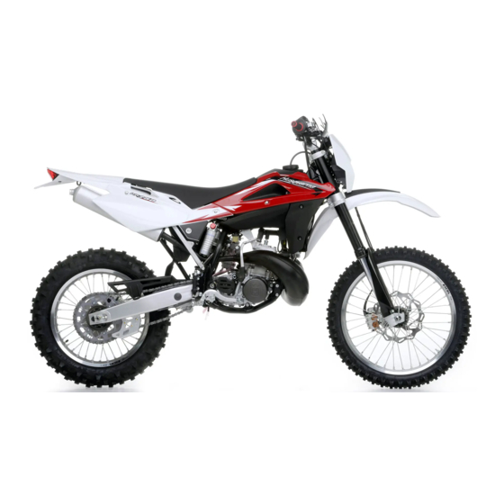
WR 250
WR 300
WR 250 2012
WR 300 2012
WR 250 2012 USA (EN)
WR 300 2012 USA (EN)
CARATTERISTICHE - USO - MANUTENZIONE
SPECIFICATIONS - OPERATION - MAINTENANCE
CARACTERISTIQUES - UTILISATION - ENTRETIEN
MERKMALE - GEBRAUCH - WARTUNG
CARACTERISTICAS - USO - MANTENIMIENTO
IT - 1
9-05-2011 16:47:48
Publicidad
Capítulos
Tabla de contenido

Manuales relacionados para Husqvarna WR 250 2012


Resumen de contenidos para Husqvarna WR 250 2012
- Página 1 WR 250 WR 300 WR 250 2012 WR 300 2012 WR 250 2012 USA (EN) WR 300 2012 USA (EN) CARATTERISTICHE - USO - MANUTENZIONE SPECIFICATIONS - OPERATION - MAINTENANCE Dove non diversamente specificato, i dati e le prescizioni si riferiscono a tutti i modelli.
-
Página 2: Presentazione
AVVERTENZE IMPORTANTI WR 250 ENDURO Benvenuti nella famiglia motociclistica Husqvarna! La Vostra nuova motocicletta Husqvarna é stata progetta- I modelli WR sono motocicli per impiego ta e costruita per essere la migliore della sua categoria. STRADALE (A POTENZA LIMITATA), garantiti... - Página 3 é dotato di elettrovento- In caso di sostituzione dei particolari, usare unicamente la e termostato. Lunghe soste al semaforo particolari ORIGINALI Husqvarna. con il motore acceso possono causare un PRECAUZIONI PER I BAMBINI surriscaldamento di quest’ultimo con l’ebol- ATTENZIONE lizione dell’acqua del radiatore.
-
Página 4: Tabla De Contenido
SOMMARIO Note Pag. • Le indicazioni di destra e sinistra si riferiscono ai due lati del motociclo rispetto al senso di marcia. PRESENTAZIONE ..............2 AVVERTENZE IMPORTANTI............2 • n° denti DATI PER L’IDENTIFICAZIONE ...........5 • Austria DATI TECNICI ................7 AUS: Australia TABELLA DI LUBRIFICAZIONE, RIFORNIMENTI ......8 Belgio COMANDI ................9... -
Página 5: Dati Per L'identificazione
DATI PER L’IDENTIFICAZIONE Il numero di identificazione del motore è stampigliato sulla par- te superiore del carter motore, mentre il numero di matricola del motociclo è stampigliato sul tubo di sterzo del telaio. Riferite sempre, annotandolo anche sul presente libretto, il numero stampigliato sul telaio quando ordinate i ricambi o chiedete informazioni sul vostro motociclo. - Página 6 UBICAZIONE COMANDI 10- Rubinetto carburante 11- Vite scarico aria per stelo forcella 1- Leva comando freno anteriore 12- Registrazione compressione per stelo forcella 2- Manopola comando gas 3- Commutatore sinistro 13- Registrazione estensione per stelo forcella 4- Pedale comando freno posteriore 14- Registrazione precarico molla ammortizzatore 5- Pedale avviamento 15- Registrazione compressione ammortizzatore (bassa ed alta velocità...
-
Página 7: Dati Tecnici
DATI TECNICI ALIMENTAZIONE RAPPORTI TOTALI DI TRASMISSIONE Tipo . . . . . . . . . . . . . . . . . . . . . Carburatore “Mikuni” TMX 38 1a velocità... -
Página 8: Tabella Di Lubrificazione, Rifornimenti
TABELLA DI LUBRIFICAZIONE, RIFORNIMENTI CERCHI Anteriore . . . . . . . . . . . . . . . . . . . . . .in lega leggera: 1,6x21” Posteriore . -
Página 9: Comandi
COMANDI CAVALLETTO LATERALE Il rubinetto incorpora un filtro; l’accumulo di sporcizia provoca Ogni motociclo è fornito di un cavalletto laterale (1). una diminuizione del passaggio di carburante verso il carbu- RUBINETTO CARBURANTE ratore. E’ pertanto necessario effettuare la pulizia nel modo seguente: Il rubinetto (1) posto sulla sinistra del serbatoio consta di tre ATTENZIONE*: Il cavalletto è... - Página 10 CARBURANTE STARTER CARBURATORE Il motociclo monta un motore a due tempi che richiede un’ali- Il pomello (1) dello starter, posto sulla sinistra del carburatore, mentazione di miscela benzina-olio. Il carburante consigliato è viene azionato per arricchire la miscela durante l’avviamento. benzina SENZA PIOMBO a 98 ottani.
- Página 11 STRUMENTO DIGITALE, SPIE - Le funzioni, che si possono selezionare nell’ordine, sono le 1- SPEED (Km/h o mph) / ODO (figura 1) seguenti: Il motociclo è equipaggiato con uno strumento digitale sul quale - SPEED: velocità del veicolo- Indicazione max: 299 Km/h o 299 sono montate anche 2 spie indicatrici: abbagliante ed indicatori 1- SPEED / ODO (figura 1) mph;...
- Página 12 3- SPEED / TRIP 1 (figura 3) 4- SPEED / CRONOMETRO (STP) (figura 4) 2- SPEED / CLOCK (figura 2) - SPEED: velocità- Indicazione max: 299 Km/h o 299 mph - SPEED: velocità- Indicazione max: 299 Km/h o 299 mph; - SPEED: velocità- Indicazione max: 299 Km/h o 299 mph;...
- Página 13 COMANDO GAS BLOCCASTERZO La manopola (1) del gas è situata sul lato destro del manubrio. Il motociclo è fornito di un bloccasterzo (1) posto sul lato destro La posizione del comando sul manubrio può essere regolata del cannotto di sterzo. allentando le due viti di fissaggio.
- Página 14 COMANDO FRIZIONE COMANDO FRENO POSTERIORE COMMUTATORE SINISTRO SUL MANUBRIO La leva della frizione è situata sul lato sinistro del manubrio ed Il pedale (1) di comando del freno posteriore si trova sul lato de- Il commutatore sinistro ha i seguenti comandi: è...
- Página 15 COMANDO CAMBIO PEDALE AVVIAMENTO La leva (1) è posta sul lato sinistro del motore. Il pilota, ad ogni Il pedale (2) è posto sul lato destro del motociclo. cambio di velocità, deve lasciare libero il pedale che tornerà nella sua posizione centrale; la posizione di “folle” (N) si trova tra la prima e la seconda marcia.
-
Página 16: Istruzioni Per L'uso Del Motociclo
ISTRUZIONI PER L’USO DEL MOTOCICLO Controllare che il filtro sia pulito. 4. Portare il motore alla normale temperatura d’esercizio. Gui- Controllare i raccordi in gomma e le fascette. dare il motociclo a velocità moderata per circa 10 minuti. Ripe- 8. Controllare il sistema di scarico CONTROLLI PRELIMINARI tere la procedura di raffreddamento precedentemente descritta. - Página 17 AVVIAMENTO DEL MOTORE NOTA IMPORTANTE IN CASO DI AVVIAMENTO A IMPORTANTE FREDDO A BASSE TEMPERATURE Non accelerare mai il motore dopo un avviamento a freddo. Per procedere correttamente all’avviamento a freddo del moto- Si raccomanda di effettuare un breve riscal- re operare nel modo seguente: damento al minimo fino a quando, dopo ATTENZIONE*: Il sistema di scarico contiene gas...
- Página 18 - Premere il pulsante (3) arresto motore. ARRESTO DEL MOTOCICLO E DEL MOTORE - Chiudere il rubinetto (4) del carburante. - Chiudere completamente la manopola (1) del gas in modo da Una volta arrestato il motociclo, porlo sul cavalletto laterale. far decelerare il motociclo.
- Página 19 CONTROLLO LIVELLO OLIO CAMBIO CONTROLLO LIVELLO LIQUIDO DI RAFFREDDA- SOSTITUZIONE OLIO CAMBIO MENTO Tenendo il motociclo in piano ed in posizione verticale, rimuove- Per sostituire completamente l’olio, svitare il tappo (A) sotto- re la vite (C) di controllo e verificare il livello attraverso il foro di Controllare il livello (1) nel radiatore destro a motore freddo coppa e lasciare defluire completamente l’olio;...
- Página 20 ATTENZIONE*: Il refrigerante sui pneumatici SOSTITUZIONE LIQUIDO DI RAFFREDDAMENTO li renderà sdrucciolevoli con potenziali rischi Effettuare la sostituzione operando, a motore freddo, nel modo di incidenti o lesioni. seguente: - rimuovere il tappo del radiatore destro; Controllare periodicamente i manicotti di collegamento (vedi - rimuovere la vite di scarico (2) sul coperchio pompa oppure il “Scheda di manutenzione periodica”);...
- Página 21 REGISTRAZIONE MINIMO REGOLAZIONE CAVO COMANDO GAS - se la lunghezza del registro (2) non fosse sufficiente a otte- nere la corretta regolazione, agire sul registro posizionato La registrazione del minimo deve essere effettuata solo a mo- La regolazione del cavo comando gas si può effettuare tramite il sul carburatore.
- Página 22 REGISTRAZIONE FRIZIONE Una ulteriore possibilità di registrazione è offerta dal tenditore (1) posto sulla destra del telaio. Se, dopo la registrazione, la La frizione non richiede, normalmente, altra regolazione che frizione slitta sotto carico o trascina anche quando é quella della tensione del cavo utilizzando il gruppo di registro disinnestata, dev’essere smontata per le opportune verifiche.
- Página 23 CONTROLLO CANDELA Prima di procedere al rimontaggio, eseguire Esatto grado termico: una accurata pulizia degli elettrodi e dell’iso- La punta dell’isolante è secca ed il colore è marrone chiaro o La candela (2) è NGK BR8EG; la distanza fra gli elettrodi deve lante usando uno spazzolino metallico.
- Página 24 PULIZIA FILTRO ARIA MONTAGGIO CONTROLLO FILTRO ARIA Lavare il filtro con un detergente specifico (CASTROL FOAM AIR Mettere del grasso sul bordo (C) del filtro dal lato dell’allog- Ruotare in senso antiorario il perno posteriore (1), rimuoverlo FILTER CLEANER o prodotto similare) ed asciugarlo perfettamen- giamen to per ottenere una buona tenuta.
- Página 25 REGOLAZIONE GIOCO DEI CUSCINETTI DELLO Mettetevi a terra di fronte al motociclo, afferrate le estremità in- STERZO feriori degli steli della forcella e muovetele in senso normale al loro asse. Se si avverte gioco occorrerà eseguire la regolazione Per motivi di sicurezza lo sterzo dovrebbe essere sempre man- operando come segue: tenuto registrato in modo tale che il manubrio di guida ruoti allentare il dado (1) del cannotto di sterzo.
- Página 26 In caso di contatto, pulire completa- mente la parte colpita e, qualora si trattas- controllare l’impianto frenante presso il Con- se degli occhi, chiamare un medico. cessionario Husqvarna. A: per aumentare il gioco B: per diminuire il gioco IT - 26 MUM1_WR250-300_2011_ITA.indd 26...
- Página 27 REGISTRAZIONE POSIZIONE PEDALE FRENO PO- REGISTRAZIONE CORSA A VUOTO FRENO POSTERIORE CONTROLLO LIVELLO FLUIDO STERIORE Il pedale di comando del freno posteriore, deve avere una corsa Il livello (A) deve trovarsi tra le tacche poste sul serbatoio pom- a vuoto (B) di 5 mm prima di inizare l’azione frenante. La posizione del pedale di comando del freno posteriore rispetto all’appoggiapiede, può...
- Página 28 REGOLAZIONE DELLE SOSPENSIONI IN BASE A TERRENO SABBIOSO NOTE PARTICOLARI CONDIZIONI DELLA PISTA Forcella: regolazione più dura in compressione, oppure sosti- Se la forcella fosse troppo morbida o troppo dura in ogni con- tuzione della molla standard con una più dura con contempo- dizione di registrazione, verificare il livello dell’olio nello stelo Le indicazioni che seguono costituiscono una guida indicativa ranea regolazione più...
- Página 29 LIVELLO OLIO FORCELLA Le tarature standard e le procedure di registrazione sono ripor- c) SFIATO ARIA (da effettuare dopo ogni gara in caso di uso tate qui di seguito. competitivo oppure mensilmente). Per il regolare funzionamento della forcella é indispensabile Porre il veicolo su un cavalletto centrale, estendere completa- che in entrambe le gambe si trovi la prevista quantità...
- Página 30 MODIFICA POSIZIONE ED ALTEZZA MANU- a) Modifica posizione manubrio b) Modifica altezza manubrio BRIO Ruotare di 180° il cavallotto inferiore per ottenere l’avanza- Rimuovere il distanziale inferiore (A) e sostituire la vite (4) mento o l’arretramento (10mm- 0.04 in.) della posizione del con una di lunghezza L=65 mm..
- Página 31 3. Con l’aiuto di una seconda persona rilevare la nuova distan- ATTENZIONE*: Non smontare mai l’ammortiz- za (A). zatore perchè contiene gas sotto pressione. Per interventi di maggiore entità rivolgersi al Concessionario Husqvarna. B: asse vite fissaggio pannello C: asse perno ruota posteriore IT - 31 MUM1_WR250-300_2011_ITA.indd 31...
- Página 32 2. Pulire la controghiera (1) e la ghiera di registro (2) della REGISTRAZIONE FRENO IDRAULICO AMMOR- B) ESTENSIONE - Taratura standard: molla (3). TIZZATORE - 15 scatti (± 2 scatti) 3. Allentare la controghiera per mezzo di una chiave a gancio o con un punzone in alluminio.
- Página 33 REGISTRAZIONE CATENA (Fig. A) Regolazione rapida (Fig. B.) Spingere la catena verso la parte terminale del pattino e verifi- La catena deve essere controllata, registrata e lubrificata in care che la distanza “A” da quest’ultimo risulti compresa tra 0 e accordo con la “Tabella di manutenzione”;...
- Página 34 CONTROLLO USURA CATENA, PIGNONE, CORONA LUBRIFICAZIONE CATENA Controllare eventuali danni o usura del pignone. Se questo pre- senta un’usura uguale a quella mostrata in figura, deve essere Controllare l’usura della catena nel modo seguente: Lubrificare la catena attenendosi alle istruzioni che seguono. sostituito.
- Página 35 Lubrificazione catena con anelli OR AVVERTENZA*: Il lubrificante per la catena 2- Controllare che la catena non sia usurata o danneggiata. NON deve venire a contatto con il pneumatico Sostituirla sempre in accordo con la Tabella di Manutenzione Lubrificare con un pennello sia le parti metalliche che quelle in o il disco freno posteriori.
- Página 36 NOTE SmONTAGGIO RUOTA ANTERIORE Con la ruota smontata, non tirare la leva del freno per non pro- Posizionare un blocco o un cavalletto sotto il motore in modo vocare l’avanzamento dei pistoncini della pinza. Dopo la rimozio- che la ruota anteriore sia sollevata dal terreno. ne, appoggiare la ruota con il disco rivolto verso l’alto.
- Página 37 Inserire dal lato destro il perno ruota (2) precedentemente in- RImONTAGGIO RUOTA ANTERIORE NOTA grassato e batterlo fino a battuta sullo stelo sinistro; mentre si Dopo aver rimontato la ruota, agire sulla leva di comando fino Montare il distanziale sinistro sul mozzo ruota. esegue questa operazione, è...
- Página 38 SmONTAGGIO RUOTA POSTERIORE NOTE Con la ruota smontata, non agire sul pedale del freno per non Svitare il dado (1) del perno ruota (3) e sfilare quest’ultimo; provocare l’avanzamento dei pistoncini della pinza. non è necessario allentare i tendicatena (2), in questo modo Dopo la rimozione, appoggiare la ruota con il disco rivolto verso il valore di tensione della catena risulterà...
- Página 39 PNEUMATICI FRENI 6. Serbatoio olio freno posteriore 7. Tubazione posteriore Abbiate cura di tenere i pneumatici gonfiati sempre alla giusta I principali componenti dei due impianti sono: la pompa freno 8. Pinza freno posteriore pressione che deve corrispondere a quella indicata a pag. 8. con relativa leva (anteriormente) o pedale (posteriormente), la 9.
- Página 40 SmONTAGGIO PASTIGLIE FRENO USURA PASTIGLIE Controllare l’usura delle pastiglie. - Rimuovere le mollette 1. Il limite di servizio”A” é: 3,8 mm . - Sfilare i perni 2. Se detto limite é stato superato, sostituire le pastiglie in coppia. - Rimuovere le pastiglie. ATTENZIONE! Non azionare la leva o il pedale freno men- tre si tolgono le pastiglie.
- Página 41 PULIZIA PASTIGLIE ATTENZIONE! Non guidare il motociclo fino a quando la Accertarsi che non ci siano tracce di fluido freni o di olio sulle leva o il pedale freno non saranno del tutto pastiglie o sui dischi. Pulire le pastiglie o i dischi da eventuali efficienti.
- Página 42 USURA DISCO FRENO SFARFALLAMENTO DISCO Misurare lo sfarfallamento del disco. Il limite di servizio per Rilevare lo spessore di ogni disco nel punto di maggiore usura. entrambi i dischi é di 0,15 mm. Sostituire il disco se l’usura ha superato il limite previsto. Sostituire il disco se lo sfarfallamento é...
- Página 43 PULIZIA DISCO Una scarsa efficienza di frenata può anche essere causata dalla presenza di olio sul disco. Olio o grasso sul disco possono essere eliminati mediante un solvente ad alto indice di infiammabilità come acetone o prodotti similari. IT - 43 MUM2_WR250-300_2011_ITA.indd 43 9-05-2011 18:03:36...
- Página 44 SOSTITUZIONE FLUIDO AVVERTENZA! Per effettuare la sostituzione, procedere nel * Usare solamente fluido freni prelevato da modo seguente: Il fluido freni deve essere controllato e sostituito in accordo con contenitore sigillato (DOT 4). Non usare la Tabella di Manutenzione o nel caso fosse stato contaminato mai fluido già...
- Página 45 - Pompare con la leva freno (3) o il pedale freno (3A) in - Ripristinare il livello (A) o (B) del fluido e rimontare il modo da evacuare completamente il fluido. soffietto in gomma ed il coperchio del serbatoio. - Chiudere la valvola di spurgo e riempire il serbatoio con fluido fresco.
- Página 46 SPURGO ImPIANTO FRENANTE ANTERIORE ATTENZIONE! Il fluido freni intacca velocemente le superfi- Lo spurgo dell’impianto frenante deve essere effettuato dopo la ci verniciate, pertanto ogni sua traccia deve sostituzione del fluido o quando, a causa della presenza di aria essere immediata mente rimossa . nel circuito, la corsa della leva diventa lunga ed elastica.
- Página 47 ATTENZIONE! - Togliere il coperchio (2) del serbatoio fluido, il soffietto in Nel caso il motociclo, durante una Durante l’operazione di spurgo, il livello del gomma e riempire il serbatoio con fluido fresco. gara, subisca delle cadute, oppure in fluido all’interno del serbatoio non deve - Allentare la valvola di spurgo ed azionare ripetutamente la seguito a riparazioni di officina, ma- mai trovarsi al di sotto della tacca di mini-...
- Página 48 SPURGO ImPIANTO FRENANTE POSTERIORE - Abbassare completamente il pedale (2). - Bloccare la valvola di spurgo alla coppia prescritta e control- - Allentare la valvola di spurgo lasciando fuoriuscire il fluido lare il livello (B) del fluido nel serbatoio prima di rimontare il Lo spurgo dell’impianto frenante deve essere effettuato dopo la (all’inizio uscirà...
- Página 49 SILENZIATORE DI SCARICO SOSTITUZIONE mATERIALE FONOASSORBENTE Nota*: Se fosse difficoltoso rimuovere il si- SILENZIATORE lenziatore, aiutarsi nell’operazione batten- Il silenziatore riduce la rumorosità di scarico ma è anche parte do leggermente con un martello in gomma Rimuovere la sella dopo aver ruotato in senso antiorario il per- integrante dell’impianto di scarico e come tale le sue condizioni o in plastica.
- Página 50 REVISIONE RUOTE DEFORmAZION E CERCHIO RAGGI RUOTA Le tabelle sono riportate mostrando i tipi di controllo a cui devo- Accertarsi che tutti i nippli siano ben stretti e, se necessario, no essere sottoposti cerchio e perno ruota. serrarli nuovamente. Una tensione insufficiente pregiudica la STANDARD LIMITE MAX.
- Página 51 SOSTITUZIONE LAmPADINE PROIETTORE - togliere il connettore (2) della lampada biluce (7) e la cuffia (3) in gomma; - Proiettore con lampada alogena biluce da 12V-35/35W e - togliere la vite (6); lampada luce di posizione da 12V-5W; - sganciare la molletta (4) di tenuta e rimuovere la lampada. - Indicatori di direzione da 12V-10W;...
- Página 52 FANALE POSTERIORE SOSTITUZIONE LAMPADA LUCE TARGA Il fanale posteriore (1) è del tipo a LED; in caso di non funziona- - Svitare la vite (1) e staccare la luce targa (2) dal parafango; mento deve essere sostituito. - estrarre il portalampada (3) con la lampadina (4) dal supor- - tirare la lampadina (4) per sfilarla dal portalampada;...
- Página 53 REGISTRAZIONE FANALE ANTERIORE L’eventuale rettifica dell’orientamento si può effettuare agendo sulla vite (1) per abbassare o alzare il fascio luminoso. Per controllare se il fanale è orientato nel modo corretto mette- re il motociclo, con in pneumatici gonfiati alla giusta pressione e con una persona seduta in sella, perfettamente perpendicolare con il suo asse longitudinale.
-
Página 54: Appendice
Per rimettere in attività il motociclo, procedere come segue: APPENDICE ATTENZIONE - Accertarsi che la candela sia serrata . Non disperdere il carburante eliminato VERIFICHE DOPO LA GARA - Riempire il serbatoio carburante. nell’ambiente e far girare il motore all’aria Dopo la gara, pulire il motociclo come sottoriportato poi ispezio- - Far girare il motore per circa 5 minuti per scaldare l’olio, do- aperta, non in ambienti chiusi. - Página 55 PULIZIA RACCOmANDAZIONE ImPORTANTE Premesso che, prima del lavaggio del motociclo, è necessario proteggere opportunamente dall’acqua le seguenti parti: a) Apertura posteriore dello scarico; b) Leve frizione e freno anteriore, manopole, commutatori sul manubrio; c) Aspirazione filtro aria; d) Testa di sterzo forcella, cuscinetti ruote; e) Leveraggi sospensione posteriore.
- Página 56 È necessario EVITARE ASSOLUTAmENTE CHE Dopo il lavaggio: GETTI D’ACQUA O D’ARIA AD ALTA PRESSIONE - Lubrificare i punti riportati nella “tabella di manutenzione” vengano a contatto con le PARTI ELETTRICHE, (Appendice A). specialmente la centralina elettronica (1) e - Avviare il motore e farlo girare per 5 minuti. il cruscotto.
-
Página 57: Operazioni Di Preconsegna
Freni / Frizione Controllo funzionalità Interruttore accensione Controllo funzionalità ❏ ❏ Freni / Frizione Controllo circuito Serrature Controllo funzionalità ❏ ❏ Comando acceleratore Controllo funzionalità ❏ Serraggio viti e dadi Controllo / serraggio ❏ 12a-senza tabelle-2004-OK 28-09-2004 16:42 Pagina 279 Comando acceleratore Verifica/regolazione gioco ❏... -
Página 58: Indice Alfabetico
INDICE ALFABETICO Pagina Liquido di raffreddamento ..............8 Rodaggio ..................16 Accensione ..................7 Livello olio forcella .................29 Rubinetto carburante..............10 Arresto del motociclo ..............18 Lubrificazione catena ..............34 Ruote ..................8, 36 Arresto del motore .................18 Lubrificazione motore..............8 Avviamento motore ................17 Sfarfallamento disco freno .............42 Modifica posizione manubrio............30 Silenziatore di scarico..............49 Bloccasterzo ...................13... - Página 59 ENGLISH EN - 1 MUM1_WR250-300_2012_GB.indd 1 9-05-2011 16:52:12...
- Página 60 WR 300 and equipment. Your Husqvarna dealer has the facilities, experience and origi- nal parts necessary to properly render this valuable service. This “Owner’s Manual” is part and par-...
- Página 61 Parts Replacement this motorcycle until you have received expert This motorcycles was not designed for urban When parts replacement is required, use only Husqvarna ORIGI- instruction and are in excellent physical condi- use and is not equiped with a cooling fan tion.
- Página 62 TABLE OF CONTENTS Note Page • References to the “left” or “right” of the motorcycle are in the sense of a person facing forwards. PRESENTATION ............... 2 IMPORTANT NOTICES .............. 2 • number of teeth IDENTIFICATION DATA ............. 5 • Austria TECHNICAL DATA ..............
-
Página 63: Identification Data
IDENTIFICATION DATA The engine number is printed on the upper side of the engi- WR 300 ne case, whereas the frame number is printed on the steering tube. Always state the number stamped on the frame ZKH3H02ACCV000001 (and write it on this booklet), when placing orders for spare parts, or when asking for information on your motorcycle. - Página 64 CONTROL LOCATION 10. Fuel cock 11. Air bleeding screw on front fork leg 1. Front brake lever 12. Compression damper adjustment (front fork leg) 2. Throttle grip 3- L.H. commutator 13. Extension damper adjustment (front fork leg) 4. Rear brake control pedal 14 .Rear shock absorber spring preload adjustment 5.
-
Página 65: Technical Data
TECHNICAL DATA FUEL SYSTEM SECONDARY DRIVE Type ..... Carburettor “Mikuni” TMX 38 ENGINE Transmission sprocket- Rear wheel sprocket ..... Z 13- Z 48 Venturi diameter ..........1.49 in. - Página 66 RIMS TABLE FOR LUBRICATION, SUPPLIES Front .............in light alloy: 1,6x21” Rear............ in light alloy: 2,15x18” Engine lubricating oil TYRES CASTROL A747 Front ..............90/90x21” Gearbox and primary drive lubricating oil Rear..............140/80x18” CASTROL POWER 1 RACING 10W-40 Cold tire pressure Engine coolant (front) (*).
- Página 67 SIDESTAND FUEL SUPPLY VALVES A fuel filter is incorporated in the fuel valves. Accumulation of The cock (1) set on left side of tank has three positions: dirt in the filter will restrict the flow of the fuel to the carbure- A sidestand (1) is supplied with every motorcycle.
- Página 68 FUEL CARBURETOR CHOKE The motorcycle is equipped with 2 stroke engine that requires The starter knob (1), located on the left side of the carburetor, is a gasoline-oil mixture. Recommended fuel: premium grade un- used to enrich the mixture during the engine start. leaded fuel (R.O.N.
- Página 69 DIGITAL INSTRUMENT, WARNING LIGHTS 1- SPEED (Km/h or mph) / ODO (figure 1) - The instrument functions are the following, as shown below. The motorcycle is equipped with a digital instrument; on the 1- SPEED / ODO (figure 1) - SPEED: motorcycle speed- maximum value: 299 Km/h or 299 instrument are located 2 warning lights too: high beam and 2- SPEED / CLOCK (figure 2 ) mph;...
- Página 70 3- SPEED / TRIP 1 (figure 3) 4- SPEED / CHRONO (STP) (figure 4) 2-2- SPEED / CLOCK (figure 2) - SPEED: motorcycle speedmaximum value: 299 Km/h o 299 - SPEED: motorcycle speedmaximum value: 299 Km/h o 299 - SPEED: motorcycle speedmaximum value: 299 Km/h o 299 mph;...
- Página 71 THROTTLE CONTROL STEERING LOCK The throttle knob (1), is located on the right hand side of the The motorcycle is equipped with a steering lock (1) on the R.H. handlebar. The position of the throttle control can be adjusted side of the steering head tube. by loosening the two fastenig screws .
- Página 72 CLUTCH CONTROL REAR BRAKE CONTROL HANDLEBAR COMMUTATOR The clutch lever is located on the left-hand side of the handlebar The rear brake control (1) is placed on the right-hand side of the 1) Engine stop button ( and is protected against dirt filtering in. The lever support is motorcycle.
- Página 73 GEAR SHIFT CONTROL KICKSTART PEDAL The kickstart pedal (1) is situated on the right-hand side of the The lever (1) is placed on the left-hand side of the engine. The motorcycle. operator must release the lever after each gear change to allow it to return to its central position before another gear change can be made.
-
Página 74: Riding
RIDING 8. Check exhaust system 2. Stop the engine, and let it cool down naturally until its tem- Check hook up, look for cracks perature is equal to the ambient air temperature. This will allow BEFORE EVERY RIDE MAKE FOLLOWING CHECKS Check muffler. - Página 75 ENGINE START IMPORTANT NOTE IN CASE OF COLD STARTS IMPORTANT AT LOW TEMPERATURES Never accelerate the engine after a cold start. For the correct start of a cold engine proceed as follows: It is recommended to briefly warm-up - shift the transmission into neutral; the engine at idle until, after having WARNING*: Exhaust contains poisonous car- - set fuel valve (1) in ON position;...
- Página 76 - Press the engine stop button (3). STOPPING THE MOTORCYCLE AND THE ENGINE - Close the fuel cock (4). When the bike is off, place it on its side stand. - Close the throttle (1) completely so that the engine will help slow down the motorcycle.
- Página 77 TRANSMISSION OIL LEVEL CHECKING COOLANT LEVEL CHECK TRANSMISSION OIL CHANGE Check level (1) in right-hand radiator when engine is cold (place By keeping the motorcycle on a flat surface and in vertical position, To completely replace the oil, unscrew the plug (A) under the the motorcycle so that it is perpendicular to the ground).
- Página 78 WARNING*: Coolant on tires will make them REPLACEMENT OF COOLING FLUID slippery and can cause an accident or injury. The cooling liquid replacement must be performed with cold motor, as follows: Periodically check the connecting hoses (see “Periodical main- - remove the R.H. radiator plug; tenance card”): this will avoid coolant leakages and consequent - remove the drain screw (2) on the pump cover or the pump engine seizure: If hoses show cracks, swelling or hardenings due...
- Página 79 THROTTLE CABLE ADJUSTMENT IDLING ADJUSTMENT - if register (2) should not provide sufficient movement to allow for correct adjustment, then adjust register placed on The throttle cable can be adjusted using the screw set on the Idling should be adjusted only when the engine is hot and throt- carburetor.
- Página 80 CLUTCH ADJUSTMENT The adjustment can be also effected with tightener (1) set on the right of the frame. Take care to tighten properly the lock The clutch is adjusted by stretching the cable using the adjusting nut. If the clutch slips under load or drags in disengaged posi- unit positioned on the handlebar.
- Página 81 SPARK PLUG CHECK Before refitting the plug, thoroughly clean the Correct heat rating: The tip of the insulator should be dry and the colour should be light electrodes and the insulator using a brass-metal Use NGK BR8EG spark plug (2); the gap is 0,6÷0,7 in. brown or grey.
- Página 82 AIR FILTER AND CLEANING ASSEMBLY AIR FILTER CHECK Wash the filter with a specific detergent (CASTROL FOAM AIR To ensure tight fit, slightly (C) grease filter edge on side facing Turn rear pin (1) counterclockwise, remove the saddle from the FILTER CLEANER or similar) then dry it fully (wash filter with filter housing.
- Página 83 STEERING WHEEL BALL PLAY ADJUSTMENT Stand in front of the motorcycle and grasp the lower end of the fork rods sliders moving them in the direction of their axis. To ensure maximum safety, the steering wheel should always Se si avverte gioco occorrerà eseguire la regolazione operando be regulated so that the handlebars steering the motorcycle come segue: rotate freely without play.
- Página 84 HUSQVARNA dealer. A: to encrease clearance B: to decrease clearance EN - 26 MUM1_WR250-300_2012_GB.indd 26...
- Página 85 REAR BRAKE PEDAL POSITION ADJUSTMENT REAR BRAKE IDLE STROKE ADJUSTMENT CHECKING THE FLUID LEVEL The rear brake foot pedal should have a (B) 5 mm (0.2 in.) idle The level (A) must be set between the pump tank notches. The position of the rear foot brake pedal as to the footrest may stroke before starting the true braking action.
- Página 86 ADJUSTING THE SUSPENSIONS ACCORDING TO SANDY GROUND NOTE: PARTICULAR TRACK CONDITIONS Fork: have a harder compression adjustment, or replace the When the fork results as either too soft or too hard for any ad- standard spring with a harder one, and make a softer compres- justment conditions, check the oil level inside the forkrod.
- Página 87 OIL FORK LEVEL The standard calibrations and the adjustment procedures are c) AIR VENT (to carry out after each competition, or monthly). shown below. Set the motorcycle on a central stand and release the fork fully For the regular fork operation, both legs must be provided with and loosen the air vent valve (D).
- Página 88 HANDLEBAR POSITION AND HEIGHT CHANGE a) Handlebar position change b) Handlebar height change Turn the lower clamp (2) 180° to move forward or backward Remove the lower spacer (A) then replace the screw (4) with a The handlebar position (a) and height (b) can be changed for (10mm- 0.04in.) the handlebar position with respect to the new one of L=65 mm (2.56 in.) height.
- Página 89 ADJUSTING THE SHOCK ABSORBER SPRING ADJUSTING THE SHOCK ABSORBER 4. The difference between these two measurements constitutes PRELOAD the “SAG” of the motorcycle’s rear end. The rear shock absorber must be adjusted according to the rider Suggested SAG: 4 in. with cold shock absorber. 3.7 in. with Proceed as follows: weight and track conditions.
- Página 90 2. Clean ringnut (1) and adjusting nut (2) of the spring (3). SHOCK ABSORBER DAMPING ADJUSTMENT B) EXTENSION - Standard calibration: 3. Either with a hook wrench or an aluminium punch, loosen - 15 clicks (± 2 clicks) Adjustment of the compression stroke is independent from the the ringnut .
- Página 91 CHAIN ADJUSTMENT (Fig. A) Fast adjustment (Fig. B.) Chain should be checked, adjusted and lubricated as per the Push the chain towards the final part of runner and check that Maintenance Chart to ensure security and prevent excessive between the two elements a distance “A” from 0 to 2 mm (0,08 wear.
- Página 92 CHECKING THE WEAR OF CHAIN, PINION AND LUBRICATING THE CHAIN Check the pinion damages or wear and replace it should the SPROCKET wear degree be as the one shown in figure. Remove the wheel and check the wear of the rear sproket teeth. Lubricate the chain following these instructions.
- Página 93 Lubricating the chain with OR WARNING: The chain oil has NEVER to get in 2 - Check that the chain is neither worn out nor damaged. If the contact with the tires or the rear brake disk. rollers or the links are damaged, replace the chain by fol- Lubricate all metallic and rubber (OR) elements using a brush, lowing the instructions given in the Periodical Maintenance and use engine oil with SAE 80-90 viscosity for the internal and...
- Página 94 NOTES REMOVING THE FRONT WHEEL Do not operate the front brake lever when the wheel has been Set a stand or a block under the engine and see that the front removed; this causes the caliper piston to move outwards. After wheel is lifted from the ground.
- Página 95 Fit the wheel axle (2) from the R.H. side, after greasing it and REASSEMBLING THE FRONT WHEEL NOTE push it to the stop on the L.H. leg; during this operation, the After reassembly, pump the brake control lever until the pads Fit the L.H.
- Página 96 REMOVING THE REAR WHEEL NOTES Do not operate the rear brake pedal when the wheel has been Unscrew the nut (1) of the wheel pin (3) and extract it. It is removed; this causes the caliper piston to move outwards. not necessary to unloose the chain adjusters (2);...
- Página 97 TIRES BRAKES 6. Rear brake oil tank 7. Rear brake hose Care should be taken to keep the tires properly inflated. See tire The mayor components are brake master cylinder with its lever 8. Rear brake caliper data for correct tire inflation pressure (page 8). Replace the tire (front) or pedal (rear), brakeline, caliper assembly and disc.
- Página 98 BRAKE PADS REMOVAL PADS WEAR Inspect pads for wear. - Remove springs (1). Service limit “ A” is: 3,8 mm (0.15 in.). - Remove pins (2). If service limit is exceeded, always replace the pads in pairs. - Remove pads. CAUTION! Don’t operate the brake lever or pedal while removing the pads.
- Página 99 PADS CLEANING WARNING! Do not attempt to ride the motorcycle until Be careful that no disc brake fluid or any oil gets on brake pads the brake lever or pedal are or discs. Clean off any fluid or oil that inadverently gets on the fully effective.
- Página 100 BRAKE DISC WEAR DISC WARPAGE Measure disc warpage. Service limit for both discs is 0,15 mm Measure the thickness of each disc at the point where it has (0.006 in.) worn the most. Replace the disc if it has worn past the service Replace the disc if warpage is more than service limit.
- Página 101 DISC CLEANING Poor braking can also be caused by oil on the disc. Oil or grease on the disc must be cleaned off with a high flash-point oil free solvent, such as acetone or lacquer thinner. EN - 43 MUM2_WR250-300_2012_GB.indd 43 9-05-2011 18:03:02...
- Página 102 FLUID CHANGE CAUTION! To replace the fluid, proceed as follows: * Use only brake fluid from a sealed con- The brake fluid should be checked and changed in accordance tainer (DOT 4). Never use old brake fluid. - Remove the rubber cap on the bleeding valve (1) or (1A). with the Periodic Maintenance Chart or whenever it is contami- * Never allow contaminants (dirt, water, - Attach a clear plastic hose to the bleeding valve on the brake...
- Página 103 - Pump with brake lever (3) or brake pedal (3A) in order to - Restore the brake fluid level (A) or (B) then reassemble the push brake fluid out of line. rubber and the fluid reservoir cap. - Close the bleeding valve and fill the reservoir with fresh brake fluid.
- Página 104 FRONT BRAKING SYSTEM BLEEDING WARNING! Brake fluid quickly ruins painted surfaces; The braking system must be bled after the fluid replacement any spilled fluid should be completely wiped or when, due to air in the circuit, the lever stroke is long and up immediately.
- Página 105 WARNING! - Remove fluid reservoir cap (2), the rubber and fill the reser- If the lever stroke gets stretchy and During the bleed operation the fluid level in- voir with fresh brake fluid. the braking action results as poor in side the reservoir must never be lower than - Open the bleeding valve and pump with brake lever (3) sev- the case of falls during competitions,...
- Página 106 REAR BRAKING SYSTEM BLEEDING Depress the pedal (2) and keep it full down. - Close the bleed union to the prescribed torque and check the Loosen bleed union letting flu- fluid level (B) inside the reservoir before reassemblle the cap The braking system must be bled after the fluid replacement id (at first, only air will come out), then, closing the un- (1).
- Página 107 EXHAUST MUFFLER REPLACING MUFFLER DEADENING MATERIAL Note*: If silencer or exhaust are difficult to remove, help to slide them apart by tapping The muffler reduces the noise of the exhaust gases, but it is an gently with a rubber or plastic hammer. First turn counterclockwise fastening rear pin (A) then remo- integral part of the exhaust as well.
- Página 108 OVERHAULING THE WHEELS DEFORMATION RIM WHEEL SPOKES The tables hereunder show the type of control the rim and wheel Check to make sure that all the nipples are tight; tighten them axle are to be submitted to. if necessary. STANDARD MAX.
- Página 109 HEADLAMP BULBS REPLACEMENT - remove the two filaments bulb (7) connector (2) and the boot - Headlamp with two filaments bulb of 12V-35/35W and park- (3); ing light bulb of 12V-5W; - remove the screw (6); - Turn signals bulb of 12V-10W; - release the bulb holding spring (4) and then the bulb itself.
- Página 110 TAIL LIGHT REPLACING THE NUMBER PLATE BULB The tail light (1) is a LED light; Replace it when it does not function. - loosen screw (1) and remove the number plate bulb (2) from the mudguard; - take bulb holder (3) and bulb (4) out of the support; - pull the bulb (4) to detach it from bulb holder.
- Página 111 ADJUSTMENT OF HEADLIGHT Adjust the preadlamp aiming by turning screw (1) to lower or lift the high beam. When checking the proper orienting of headlight, inflate tires at right pressure, sat a person on the saddle and place the mo- torcycle perpendicular with its longitudinal axis 10 meter (33 ft) from a wall or screen.
-
Página 112: Appendix
APPENDIX WARNING To put the motorcycle back into the use after storage. Never litter the environment with fuel, and - Make sure the spark plug is tight. AFTER-RACE CHECK POINTS let the engine running in open air, never in - Fill the fuel tank. After racing, first clean the motorcycle and then inspect the closed rooms. - Página 113 CLEANING IMPORTANT RECOMMENDATION Premised that, before the motorcycle washing, it is necessary to protect opportunely from the water the following parts: a) Rear opening of the muffler; b) Clutch and brake levers, hand grips, handlebar commuta- tors; c) Air cleaner intake; d) Fork head, wheel bearings;...
- Página 114 it is necessary ABSOLUTELY TO AVOID THAT After washing: HIGH PRESSURE JETS OF WATER OR AIR come - Lubricate the points listed in the Maintenance Table (Appendix A). to contact with THE ELECTRICAL PARTS, espe- - Start the engine and run it for 5 minutes. cially the electronic control unit (1) and the - Test the brakes before riding the motorcycle.
-
Página 115: Notes For Usa/Cdn Model
Noise emission warranty HUSQVARNA MOTORCYCLES S.R.L.. warrants that this exhaust system, at the time of sale, meets all applicable U.S. EPA Federal noise standards. This warranty extends to the first person who buys this exhaust system for purposes other than resale, and to all subsequent buyers. - Página 116 Tampering warning Warning statement Tampering with Noise Control System Prohibited. This product should be checked for repair or replacement if the Federal law prohibits the following acts or causing thereof: motorcycle noise has increased significantly through use. (1) The removal or rendering inoperative by any person other Otherwise, the owner may become subject to penalties under than for purposes of maintenance, repair, or replacement, state and local ordinances.
- Página 117 SPARK ARRESTER Note*: If silencer or exhaust are difficult to remove, help to slide them apart by tapping The WR models are equipped with a U.S. Forest Service approved gently with a rubber or plastic hammer. spark arrester for maximum efficienty and performance. C: remove the four screws (4) and the endcap (5) from si- “...
-
Página 118: Notes For "Aus" Model
NOTES FOR “AUS” MODEL (WR 250-300 USA) Tampering Warning: Tampering with Noise Control System Prohibited. Federal law prohibits the following acts or causing therefor: 1) The removal or rendering inoperative by any person other than for purposes of maintenance, repair, or replacement, of any device or element of design incorporated into any new vehicle for the purpose of noise control prior to its sale or delivery to the ultimate purchaser or while it is in use, and 2) The use of the vehicle after such device or element of design has been removed or rendered inoperative by any person. -
Página 119: Pre-Delivery Inspection
Freni / Frizione Controllo circuito ❏ Serrature Controllo funzionalità ❏ Comando acceleratore Controllo funzionalità ❏ Serraggio viti e dadi Controllo / serraggio ❏ Fascette stringitubo Controllo / serraggio Comando acceleratore Verifica/regolazione gioco ❏ ❏ Comando starter Controllo funzionalità Lubrificazione generale ❏... - Página 120 ALPHABETIC INDEX Page Digital instrument ................11 Notes for USA/CDN model ............57 Adjusting the carburetor ...............21 Driven transmission chain ..............7 Notes for “AUS“ model ..............60 Adjusting the clutch ..............22 Adjusting the driven transmission ..........33 Adjusting the fork ................29 Engine lubrication ................8 Overhauling the wheels ..............50 Adjusting the front brake control lever .............26 Engine start ................17...
- Página 121 FRANÇAIS FR - 1 MUM1_WR250-300_2012_FR.indd 1 9-05-2011 16:51:01...
- Página 122 ENDURO Bienvenus dans la famille motocycliste Husqvarna! Les modèles WR êtes motocycles pour emploi Votre nouvelle moto Husqvarna a été projetée et construite ROUTIER (AVEC LA PUISSANCE LIMITÉ) garantis pour qu’elle soit la meilleure dans son genre. Les instructions exempté par défauts et couvert par garantie de service ci-incluses ont été...
- Página 123 Pour assurer un usage sans aléa, remplacer les plusieurs du moteur avec l’ébullition de l’eau dans le éléments avec des éléments ORIGINAUX Husqvarna. PRECAUTIONS POUR LES ENFANTS ATTENTION radiateur. •...
- Página 124 RESUME Avis Page • Les indications “droite” et “gauche” se refèrent aux deux côtés du motocycle par rapport au sens de marche. PRESENTATION ...............2 AVIS IMPORTANT ..............2 • numéro dents ELEMENTS D’IDENTIFICATION ..........5 • Autriche DONNEES TECHNIQUES ............7 AUS: Australie TABLEAU DE GRAISSAGE, RAVITAILLEMENTS ......8 Belgique COMMANDES ................9...
- Página 125 ELEMENTS D’IDENTIFICATION Le numéro d’identification moteur est gravé sur la partie supérieure du carter moteur, tandis que le numéro de matricule de la moto est gravé sur le tube de direction du cadre. Veuillez noter sur ce livret le numéro gravé sur le cadre, auquel on doit toujours se référer lors d’une commande de pièces de rechange, ou lors d’une demande d’informations sur votre motocycle.
- Página 126 POSITION DES COMMANDES 10. Robinet carburant 11. Vis de sortie d’air pour tige fourche 1. Levier commande frein avant 2. Poignée de gaz 12. Réglage compression pour tige fourche 3. Commutateur gauche 13. Réglage extension pour tige fourche 4. Pédale commande frein arriere 14.
- Página 127 DONNEES TECHNIQUES ALIMENTATION TRANSMISSION SECONDAIRE MOTEUR Type..........Carburateur “Mikuni” TMX 38 Pignon sortie boîte de vitesse- Couronne sur la roue ..Z 13- Z 48 Type............un cylindre à 2 temps Diamètre diffuseur ............mm 38 Rapport de transmission ..........3,692 Refroidissement .............liquide Gicleur principal ..............
- Página 128 JANTES TABLEAU DE GRAISSAGE, RAvITAILLEmEnTS Avant ..........en alliage léger: 1,6x21” Arrière ..........en alliage léger: 2,15x18” Huile de graissage moteu PNEUS CASTROL A747 Avant ..............90/90x21” Arrière ..............140/80x18” Huile de graissage boîte des vitesses, transmission primaire CASTROL POWER 1 RACING 10W-40 Pression de gonflage a froid (avant) (*) .
- Página 129 COMMANDES BEQUILLE LATERALE Le robinet a un filtre; la crasse s’accumulant dans ce filtre cause une diminution de carburant vers le carburateur. Il faudra donc Chaque motocycle est doté d’une béquille latérale (1). ROBINETS CARBURANT nettoyer le filtre comme suit: 1 - Oter le carburant dans le réservoir et la tuyauterie aussi.
- Página 130 CARBURANT STARTER CARBURATEUR Le motocycle monte un moteur à deux temps et il demande donc Le pommeau (1) du starter, placé à gauche du carburateur, un mélange essence-huile. Carburant recommandé: essence sert à enrichir le mélange durant le démarrage. SANS PLOMB à 98 octanes. Tirer le pommeau vers le haut pour ouvrir le starter, et renverser l’opération pour le fermer.
- Página 131 INSTRUMENT DIGITAL, VOYANTS -- Les fonctions, qu’ils peuvent sélectionner dans l’ordre, sont les 1- SPEED (Km/h o mph) / ODO (figure 1) suivante: Le motocycle est équipé avec un instrument digital sur lequel - SPEED: vitesse du véhicule - Indication max: 299 km/h ou 299 1- SPEED / ODO (figure 1) sont montées 2 voyants indicateurs aussi: de route et indicateurs 2- SPEED / (figure 2 )
- Página 132 3- SPEED / TRIP 1 (figure 3) 4- SPEED / CHRONOMETRE (STP) (figure 4) 2- SPEED / CLOCK (figure 2) - SPEED: vitesse du véhicule - Indication max: 299 kmh ou 299 - SPEED: vitesse du véhicule - Indication max: 299 kmh ou 299 - SPEED: vitesse du véhicule - Indication max: 299 km/h ou mph;...
- Página 133 POIGNEE DES GAZ BLOC DE DIRECTION La poignée (1) des gaz est placée à droite du guidon. La position de A droite de la moto a été assemblé un bloc-direction (1). la commande sur le guidonpeut être réglée en desserant les deux Pour bloquer la direction, agir comme suit: tournee le guidon à...
- Página 134 COMMANDE DE L’EMBRAYAGE COMMANDE FREIN ARRIERE COMMUTATEUR GAUCHE SUR LE GUIDON Le levier de l’embrayage est situé à gauche sur le guidon et il La pédale (1) de commande du frein arrière se trouve du côté droit Le commutateur gauche a les fonctions suivantes: est muni d’une protection.
- Página 135 COMMANDE DU CHANGEMENT DE VITESSES PEDALE DE DEMARRAGE MOTEUR La pédale (2) est située du côté droite de la moto. Le levier (1) est placé sur le côté gauche du moteur. A chaque changement de vitesse, le conducteur doit libérer la pédale qui retournera dans sa position centrale avant de passer à...
- Página 136 IMODE D’EMPLOI DE LA MOTO 8. Contrôle du système d’échappement Conduire la motocyclette à une vitesse modérée pendant envi- Contrôler les montages et vérifier les ruptures éventuelles ron 10 mm. Répéter la procédure de refroidissement d’ecrite Contrôler les silencieux. CONTROLES PRELIMINAIRES précédemment.
- Página 137 DÉMARRAGE DU MOTEUR NOTE IMPORTANT DANS LE CAS DE LA MISE EN IMPORTANT ROUTE A’ FROID ET TEMPERATURES BAS Le moteur froid, éviter les brusques accélérations. Pour démarrer correctement le moteur à froid, opérer comme C’est conseiller de effectuer un bref chauffage suit: au minimum, après avoir débrancher le star- ATTENTION*: Le système d’échappement...
- Página 138 - Presser le bouton (3) d’arrêt moteur. ARRET DU MOTOCYCLE ET DU MOTEUR - Fermer le robinet d’essence (4). - Fermer la poignée (1) des gaz tout, de façon à réduire la Une fois le véhicule à l’arrêt, appuyer celui-ci sur la béquille vitesse du motocycle.
- Página 139 CONTROLE DU NIVEAU D’HUILE DU BOITE DE CONTROLE DU NIVEAU REFRIGERANT VIDANGE D’HUILE BOITE DE VITESSE VITESSE Contrôler le niveau (1) dans le radiateur droit avec moteur arrêté Pour remplacer complètement l’huile, dévisser le bouchon (A) et motocycle en position verticale. Le réfrigérant doit se trouver à se trouvant au dessous de la cuve de l’huile et laisser couler Garder la moto à...
- Página 140 ATTENTION * : Le fluide réfrigérant sur les SUBSTITUTION DU LIQUIDE DE REFROIDISSEMENT pneus pourrait provoquer des glissements Efectuer le replacement avec moteur froid, de cette façon: de la roue et donc, des - enlever le bouchon du radiateur droite; accidents sérieux.
- Página 141 REGLAGE DU CABLE DE COMMANDE DES GAZ REGLAGE DU RALENTI - lorsque la longueur de la vis de réglage (2) ne permet pas d’obtenir un réglage correct, agir sur la vis de réglage placée Le réglage du câble de commande gaz s’obtient par la vis de Effectuer ce réglage avec moteur chaud et commande des gaz sur le carburateur.
- Página 142 REGLAGE DE L’EMBRAYAGE Le réglage peut être effectué même par le tendeur (1), situé à droite du cadre. Si après le règlage l’embrayage glisse ou en- L’embrayage ne demande qu’un réglage de la tension de son traîne, même en débrayant, le désassembler pour le contrôler. câble.
- Página 143 CONTROLE DE LA BOUGIE D’ALLUMAGE Avant de remonter la bougie, nettoyer Degré thermique exact: La pointe de l’isolant est sèche et sa couleur est marron clair ou soigneusement les électrodes et l’isolant en Bougie (2) de type NGK BR8EG; la distance entre les électrodes utilisant une brosse métallique.
- Página 144 NETTOYAGE FILTRE A AIR MONTAGE CONTROLE FILTRE A AIR Laver le filtre avec un détergent spécifique (CASTROL FOAM AIR Pour avoir une bonne étachéité, graisser le borde (C) du filtre dans la Tourner le pivot arrière (1) en sans antihoraire, enlever la selle de la FILTER CLEANER ou produit similaire) et lui essuyer parfaitement direction du logement.
- Página 145 REGLAGE DU JEU DES PALIERS DU GUIDON Se placer devant la moto, saisissez les extrémités inférieures des porte tiges de fourche en les mouvant dans le sens de leur axe. Pour que la sécurité soit garantie, le guidon devrait toujours être En présence d’un jeu, effectuer un réglage comme suit: parfaitement réglé...
- Página 146 éviter tout le Concessionnaire Husqvarna. contact avec la peau et les yeux. Nettoyer la partie atteinte, et s’il s’agit des yeus, appeler un médécin.
- Página 147 REGLAGE POSITION PEDALE FREIN ARRIERE RÉGLAGE DE LA COURSE À VIDE DU FREIN ARRIèRE CONTROLE DU NIVEAU FLUIDE La pédale de contrôle du frein arrière doit avoir une course à vide Le niveau (A) doit être situé entre les encoches sur le réservoir La position du pedal de contrôle frein arrière par rapport au repose- (B) de 5 mm avant de commencer le freinage.
- Página 148 REGLAGE DES SUSPENSION PAR RAPPORT AUX TERREIN SABLEUX NOTE: CONDITIONS DE LA PISTE Fourche: réglage en compression plus raide, ou remplacer le Si la fourche est trop souple ou trop raide dans n’importe ressort standard avec un ressort plus raide, avec réglage de la quelle condition de réglage, contrôler le niveau d’huile dans Les instructions suivantes sont une guide pour la mise en compression plus souple, tandis que le réglage de l’extension...
- Página 149 NIVEAU D’HUILE DE LA FOURCHE Les tarages standard et les procédures de règlage sont c) EVENT D’AIR (à effectuer après chaque compétition, ou tous indiquées ici desosus. les mois). Pour un fonctionnement correct, les tiges de la fourche doivent Placer la moto sur la béquille centrale et détendre complètement avoir la quantité...
- Página 150 MODIFICATION DE LA POSITION ET DE L’HAUTEUR a) Modification de la position du guidon b) Modification de l’hauteur du guidon DU GUIDON Tourner le etau inférieur (2) de 180° pour avancer ou reculer Enlever l’entertoise inférieur (A) et remplacer la vis (4) avec (10mm - 0.04in.) la position du guidon en relation à...
- Página 151 3. A l’aide d’une autre personne, relever la nouvelle distance (A). l’amortisseur car il contien du gaz sous pression. Pour des interventions plus importantes, contacter le Concessionnaire B: axe de la vis de fixation panneau Husqvarna. C: axe du pivot roue arrière FR - 31 MUM1_WR250-300_2012_FR.indd 31 9-05-2011 16:51:20...
- Página 152 2. Nettoyer le contre-collier (1) et le collier de réglage (2) du res- REGLAGE AMORTISSEUR HYDRAULIQUE B) EXTENSION - Tarage standard: sort (3). - 15 clicks (± 2 clicks) La course de compression peut être réglée séparément de celle 3. Desserrer le contre-collier à l’aide d’une clé à crochet, ou d’un d’extension.
- Página 153 REGLAGE DE LA CHAINE (Fig. A) Réglage rapide (Fig. B) Pousser la chaîne vers le partie final des patin en contrôlant Pour prévenir l’usure excessive et pour des raisons de sécurité, que la distance “A”des deux éléments soit comprise entre 0 et contrôler, lubrifier et régler la chaîne en suivant les instructions du 2 mm.
- Página 154 CONTROLE USURE CHAINE, PIGNON ET COURONNE LUBRIFICATION CHAINE Contrôler l’usure ou les dommages éventuels du pignon, et le remplacer s’il présente une usure égale à celle montrée par la Agir comme suit: Lubrifier la chaîne en suivant les instructions reportées ci-dessous. figure..
- Página 155 Graissage de la chaîne avec bagues d’étanchéité OR AVIS*: Le lubrifiant de la chaîne NE DOIT 2 - Contrôler que la chaîne ne soit pas usée ou endommagée JAMAIS entrer en contact du pneu ou du et la remplacer en suivant les instructions données dans le Lubrifier les éléments en métal et en cautchouc (bagues disque frein arrière.
- Página 156 NOTE Démontage de la roue avant Lorsque la roue est démontée, ne pas tirer la poignée du frein, pour Placet une béquille ou un block dessous le moteur, de façon à ne pas faire avancer les pistons de l’ etrier. Après le démontage de avoir la roue avant soulevée du sol.
- Página 157 Insérer par le côté droit le pivot de la roue (2) préalablement RéMONTAGE DE LA ROUE AVANT NOTE graissé et le battre jusq’à la butée sur la tige gauche; pendant Après le rémontage de la roue avant, actionner le levier du frein Insérer l’entertoise gauche sur le moyeau de la roue.
- Página 158 DéMONTAGE DE LA ROUE ARRIèRE NOTE Lorsque la roue est démontée, ne pas baisser la pédale du Dévisser l’écrou (1) du pivot roue (3) et extraire ce dernier; il frein, pour ne pas faire avancer les pistons de l’ etrier. n’est pas nécessaire de desserrer les tendeurs chaîne (2);...
- Página 159 PNEUS FREIN 4. Etrier avant 5. Disque avant Garder les pneus gonflés à la pression exacte, comme indiqué à Eléments principaux des deux systèmes: pompe frein avec levier 6. Réservoir à huile du frein arrière page 8. (avant) ou pédale (arrière), tubulure, étrier et disque. 7.
- Página 160 DEMONTAGE DES PASTILLES DU FREIN USURE DES PASTILLES Contrôler l’usure des pastilles. - Enlever les ressorts (1). Limite de service “A”: 3,8 mm. - Enlever les pivots (2). Si cette limite est atteinte, remplacer les deux pastilles. - Enlever les pastilles. ATTENTION! Ne pas actionner le levier ou la pédale du frein dans la phase de démontage des...
- Página 161 NETTOYAGE DES PASTILLES ATTENTION! Avant de conduire la moto, s’assurer du bon S’assurer qu’il n’y a pas trace de fluide des freins ou d’huile sur fonctionnement du levier ou de la pédale. les pastilles ou les disques. Si nécessaire, les nettoyer avec de Actionner le levier ou la pédale jusqu’à...
- Página 162 USURE DES DISQUES FREINS DISQUE PAPILLOTANT Mesurer le papillotement du disque. La limite de service pour les Relever l’épaisseur de chaque disque au point de plus grande deux disques est de 0,15 mm. usure et lorsque la limite prévue est atteinte, le remplacer. Remplacer le disque si cette limite est atteinte.
- Página 163 NETTOYAGE DU DISQUE S’il y a de l’huile sur le disque, l’action de freinage resultera nulle. L’huile ou la graisse sur le disque peuvent être éliminées en utilisant un solvant avec un haut indice d’inflammabilité comme acétone, ou produits similaires. FR - 43 MUM2_WR250-300_2012_FR.indd 43 9-05-2011 18:22:33...
- Página 164 REMPLACEMENT DU FLUIDE ATTENTION! Pour effectuer la substitution procéder de la * Utiliser seulement du fluide pris d’un réci- manière suivante: Contrôler et remplacer le fluide des freins en suivant les pient sigillé (DOT 4). Ne jamais utiliser du instructions du tableau d’entretien, au cas où de l’eau ou de la - Enlever le capuchon en gomme sur la soupape de curage (1) fluide usé.
- Página 165 - Actionner le levier (3) ou la pédale (3A) pour vidanger. - Rétablir le niveau (A) o (B) du fluide et remonter le soufflet - Fermer la soupape de curage et remplir le réservoir avec du en gomme et le couvercle du réservoir. fluide nouveau.
- Página 166 CURAGE INSTALLATION DE FREINAGE AVANT ATTENTION! P u i s q u e l e f l u i d e d e s f r e i n s r o n g e Le curage du système de freinage doit être exécutée après la rapidement les surfaces vernissées, nettoyer substitution du fluide ou lorsque, à...
- Página 167 ATTENTION! - Enlever le couvercle (2), le souffle en gomme et remplir le Si après une chute durant une compé- Pendant l’opération de curage le niveau du réservoir avec du fluide nouveau. tition, ou à la suite d’opérations fluide, à l’intérieur du réservoir, ne doit - Desserrer la soupape de curage et actionner maintes fois le d’entretien à...
- Página 168 CURAGE DU SYSTEME DE FREINAGE ARRIERE - Baisser complètement la pédale (2). - Bloquer la soupape de curage à la couple de serrage prévue et - Desserrer la soupape de curage en laissant couler le fluide (au débur contrôler le niveau (B) du fluide dans le réservoir avant de remonter Le curage du système de freinage doit être effectué...
- Página 169 SILENCIEUX D’ECHAPPEMENT Note * : Si vous avez des difficultés à ôter Enlever la selle après avoir tourné dans le sens inverse des le silencieux, battre doucement avec un aiguilles d’une montre le pivot arrière (A) de Le silencieux fait partie intégrante du système d’échappement marteau en caoutchouc ou en plastique.
- Página 170 REVISION DES ROUES DEFORMATION JANTE RAYONS DE ROUE Les tableaux ci-dessous montrent les types de contrôle auxquels S’assurer que tous les nipples soient bien serrés et, le cas la jante et l’axe de roue doivent être soumis. échéant, les serrer de nouveau. Une tensions insuffisante STANDARD LIMITE MAX.
- Página 171 REMPLACEMENT DES AMPOULES DU PHARE - ôter le connecteur (2) de l’ampoule à deux feux (7) et le protec- - Phare avant avec ampoule à deux feux de 12V-35/35W et teur (3) en caoutchouc; ampoule de feux de position de 12V-5W; - enlever la vis (6);...
- Página 172 REMPLACEMENT DE L’AMPOULE D’ÉCLAIRAGE FEU ARRIÈRE Le feu arrière (1) est de type à DEL ; en cas de dysfonctionne- DE LA PLAQUE D’IMMATRICULATION ment, il doit être remplacé. - Dévisser la vis (1) et retirer le feu de la plaque (2) du garde- boue ;...
- Página 173 REGLAGE DU PHARE AVANT Le calage de l’orientation du phare s’obtien en agissant sur la vis (1) pour baisser ou laisser le fascieau lumineux. Pour contrôler la correcte orientation du phare, placer la moto perpendiculaire à son axe longitudinal avec pression de gon- flage des pneus correcte et avec un passager assis sur la selle.
- Página 174 Pour remettre le motocycle en état de marche, opérer comme APPENDICE ATTENTION suit: Ne pas jeter le carburant éliminé dans la CONTROLES APRES CHAQUE COMPETITION nature et ne pas faire tourner le moteur - Assurez-vous que la bougie soit bien serrée. Après chaque compétition, nettoyer le motocycle en suivant dans des lieux clos mais seulement en plein - Remplir le réservoir carburant.
- Página 175 NETTOYAGE RACCOMANDATION IMPORTANTE Dit d’abord que, premier du lavage du motocycle, il est né- cessaire de protéger de l’eau opportunément les parties sui- vantes: a) Ouverture arrière d’échappement; b) Leviers d’embrayage et du frein avant, pignées, commuta- teurs sur le guidon; c) Suction filtre à...
- Página 176 Il est nécessaire, éVITER ABSOLUMENT QUE Après le lavage: JETS D’EAU OU D’AIR À la HAUTE PRESSION ils - Lubrifier les points indiqués au Tableau d’Entretien (Appendice viennent au contact avec les PARTIES éLECTRI- QUES, spécialement le centrale électronique - Démarrer le moteur et le laisser tourner pour 5 minutes. (1) et le tableau de bord.
- Página 177 Comando acceleratore Controllo funzionalità Serraggio viti e dadi Controllo / serraggio ❏ ❏ Comando acceleratore Verifica/regolazione gioco Fascette stringitubo Controllo / serraggio ❏ ❏ Comando starter Controllo funzionalità ❏ Lubrificazione generale ❏ 12a-senza tabelle-2004-OK 28-09-2004 16:42 Pagina 280 Trasmissioni e com. fless. Controllo / Regolazione ❏...
- Página 178 INDEX ALPHABETIQUE Page Embrayage ..................7 Réglage position pédale frein arrière ..........27 Réglage précharge ressort amortisseur ..........31 Allumage ..................7 Réglage suspensions selon les conditions de la piste .....28 Arrêt moteur ................18 Graissage chaîn ................34 Regulateur de tension ..............23 Arrêt motocycle ................18 Graissage moteur.
- Página 179 DEUTSCH DE - 1 MUM1_WR250-300_2012_DE.indd 1 9-05-2011 16:49:40...
- Página 180 WICHTIGE ANWEISUNGEN WR 250 ENDURO Ein Willkommen in der Familie der Motorradfahrer Hus- qvarna! Ihr neues Motorrad Husqvarna ist so entworfen WR sind STRAßE GESETZLICHE Motorräder und hergestellt worden, um das beste in seiner Klasse (mit beschränktem MACHT-MOTOR); sie wer- darzustellen.
- Página 181 Absturz des Motorrads verursa- Austausch der Teile Heizkörpern kochen. Dieses Motorrad wur- chen, mit Verletzungsgefahr von Personen Im Falle des Austausches von Teilen, nur Original-Husqvarna- de für die Wettkämpfe und den Abschluß und vor allem Kindern. Teile mit entsprechenden Merkmalen einschließlich Typ, Wider- gelernt es garantiert die besten Leistungen •...
- Página 182 INHALTSANGABE Anmerkungen Seite • Die Angaben, rechts und links, beziehen sich auf die beiden Motorrad- seiten in Bezug auf die Fahrtrichtung EINFÜHRUNG................2 WICHTIGE ANWEISUNGEN ............2 • Zähne nummer DATEN ZUR IDENTIFIZIERUNG...........5 • Österreich TECHNISCHE DATEN ..............7 AUS: Australien SCHMIERUNGSTABELLE, TANKEN ..........8 Belgien Brasilien STEUERUNGEN .................9...
- Página 183 DATEN ZUR IDETIFIZIERUNG Die Identifizierungsnummer des Motors ist auf den oberen Teil des Motorcarters gestempelt, während die Kennummerdes Mo- torrads auf das Lenkrohr des Rahmens gestempelt ist. Bei Bestellung von Ersatzteilen oder Anfragen über Ihr Motorrad ist immer die auf anzugeben. Diese Nummer ist eben- falls in die vorliegenden Betriebsanleitungen einzutragen.
- Página 184 10. Treibstoffhahn LAGE DER SCHALTUNGEN 11. Ablaßschraube für Gabelschaft 1 Vorderer Bremsschalthebel 12. Kompressions-Einstellung für Gabelschaft 2. Gasgriff 3. L. Umschalter 13. Einstellung der Ausfederung des Gabelschafts 4. Pedal zur Steuerung der Bremse 14. Einstellung der Federvorladung des Stoßdämpfers 5- Anlassenpedal 15.
- Página 185 TECHNISCHE DATEN KRAFTSTOFF FORDERUNG SEKUNDÀRÜBERSETZUNG Typ . . . . . . . . . . . . . . . . . . . . . . . .Vergaser “Mikuni” TMX 38 Abtriebsritzel- Wechselradkranz .
- Página 186 FELGE SCHMIERUNGSTABELLE, TANKEN Vorder . . . . . . . . . . . . . . . . . . . . . . aus Leichtmetall: 1,6x21” Hinter .
- Página 187 STEUERUNGEN SEITLICHE FUSSRASTE Der Hahn enthält einen Filter ; die Ansammlung von Schmutz verursacht eine Verminderung des Treibstoffdurchflusses zum Jedes Motorrad ist mit einer seitlichen (1) Fußraste ausgestat- TREIBSTOFFHÄHNE Vergaser. Es ist daher erforderlich, die Reinigung folgenderma- tet. ßen vorzunehmen : Der Hahn (1) auf der linken Seite des Behaelters hat drei Stel- 1- Den Tank vom Treibstoff befreien, die Rohrleitung abtren- ACHTUNG* :...
- Página 188 TREIBSTOFF STARTER VERGASER ACHTUNG* : Den Tank nicht über die untere Das Motorrad besitzt einen Zweitakt-Motor, der Öl-Benzin- Grenze des Einfüllstutzens füllen. Nach dem Den Knopf (1) des Starters, auf die linke Seite des Vergaser, wird Mischung-Versorgung verlangt. Empfohlener Treibstoff ist BLEIF- Tanken sich vom richtigen Verschluß...
- Página 189 DIGITALINSTRUMENT, KONTROLLLAMPEN - Folgende Funktionen können nacheinander in der angegebe- 1- SPEED (Km/h o mph) / ODO (bild 1) nen Reihenfolge ausgewählt werden: Das Motorrad ist mit einem Digitalinstrument ausgestattet, - SPEED: Motorradgeschwindigkeit - maximaler Wert : 299 an dem sich auch 2 Kontrolllampen befinden: Fernlicht und 1- GESCHWINDIGKEIT / GESAMT-KILOMETERZANZEIGE Km/h oder 299 mph;...
- Página 190 3- SPEED / TRIP 1 (Bild 3) 4- SPEED / CRHOMETER (STP) (Bild 4) 2- SPEED / CLOCK (bild 2) - SPEED: Motorradgeschwindigkeit - maximaler Wert : 299 - SPEED: Motorradgeschwindigkeit - maximaler Wert : 299 - SPEED:Motorradgeschwindigkeit - maximaler Wert : 299 Km/h oder 299 mph;...
- Página 191 GASANLASSER LENKERBLOCKUNG Der Griff (1) für das Gas, der sich auf der rechten Seite des Das Motorrad ist mit einer Lenkerblockung ausgerüstet (1), die Lenkers befindet. Die Schaltungs-Position auf dem Lenker kann sich auf der rechten Seite des Lenkers befindet. durch Lockern der beiden Befestigungsschrauben eingestellt Um den Lenker zu blockieren, folgendermassen vorgehen: den werden.
- Página 192 KUPPLUNGSHEBEL PEDAL ZUR STEUERUNG DER BREMSE HUMSCHALTER AUF DEM LENKER-LINKE KUPPLUNGSSTEUERUNG Das Pedal (1) zur Steuerung der hinteren Bremse befindet sich Der linke Umschalter hat folgende Bedienteile: Der Kupplungshebel befindet sich auf der linken Seite des auf der rechten Seite des Motorrads. Bei der Bremsung laesst 1) Druckknopf Motoranhalten ( Lenkers und ist mit einer Schutzvorrichtung ausgestattet.
- Página 193 WECHSELGETRIEBESTEUERUNG ACHTUNG* : Nicht durch Herunterschalten ANLASSPEDAL der Gänge verlangsamen bei einer Geschwin- Der Hebel (1) befindet sich auf der linken Seite des Motors. Das Pedal (2) befindet sich auf der recht Seite des Motorrads. digkeit, die den Motor “auf Touren” bringen Nach jeder Schaltung soll der Fahrer den Hebel, der von selbst könnte oder die Hinterradhaftung verlieren in seine Zentralstellung zurückkehrt, loslassen;...
- Página 194 DASS MOTORRAD 7. Den Luftfilter und das Ansaugesystem 2. Den Motor ausschalten und ihn sich auf natürliche Art bis zu kontrollieren. Raumtemperatur abkühlen lassen: das wird die korrekte Lage- VORKONTROLLEN Sich vergewissern, dass der Filter sauber ist. rung des Kolbens im Zylinder ermöglichen. ACHTUNG! Die Anschlusstücke aus Gummi und die Schlauchbinder 3.
- Página 195 ES BEMERKT WICHTIG: WICHTIG MOTORANLASSEN Starter zu kaltem des Motors in Anwesen- Bei Kaltstart Motor keinesfalls beschleunigen. Um korrekt den Kaltstart des Motors vorzunehmen, gehen Sie heit von niedrigen Umwelt Temperaturen Sie folgenderweise vor: empfiehlt, zu das geringst eine kurze Erwär- ACHTUNG * : Die Auspuffanlage enthält Koh- - das Getriebe auf Neutral schalten;...
- Página 196 MOTORANHALT UND MOTORSTILLSTAND - Den Treibstoffhane (4) schliessen. - Das Gazgriff (1) vollständig schließen , daß das Motorrad Nach dem Anhalten muss das Fahrzeug auf dem Seitenständer verlangsamt. abgestellt werden. - Sowohl vorn als auch hinten beim Herunterschalten der Gän- ge bremsen (zur starken Verlangsamung, entschieden Hebel und Bremspedale betätigen).
- Página 197 KONTROLLE OLPEGEL WECHSELGETRIEBE KONTROLLE PEGEL KÜHLFLÜSSIGKEIT ERSETZUNG ÖL WECHSELGETRIEBE Das Motorrad flach und in vertikaler Position aufstellen, die Kon- Den Stand (1) im rechten Kühler bei stillstehendem Motor und Um das Öl zu ersetzen wird man de Stöpsel (A) under der Wan- trollschraube (C) entfernen und den Stand durch das Schrauben- mit Motorrad in vertikaler Position überprüfen.
- Página 198 - das Motorrad senkrecht positioneren und überprüfen, dass AUSTAUSCH KÜHLFTÜSSIGKEIT der Stand das Kühlmittels soll ca. 10 mm über den Kühler- Das Auswechseln bei kaltem Motor ausgeführt werden: block liegen (anderfalls, mit der Nachfüllung vorgehen); - den Stopfen des rechten Küler netfernen; - den Stopfen des rechten Küler schrauben.
- Página 199 EINSTELLUNG DES GASSEILZUGS EINSTELLUNG DREHZAHLMINIMUM - falls die Laenge des Reglers (2) fuer eine fachgerechte Ein- stellung nicht ausreicht, auf den Regler wirken, der sich auf Die Einstellung des Gaskabels kann mit dem Register auf der Die Einstellung des Drehzahlminimums darf nur bei warmem dem Vergaser befindet.
- Página 200 KUPPLUNGSEINSTELLUNG Die Spannvorrichtung (1) auf der rechten Seite des Rahmens bietet eine weitere. Einstellungsmöglichkeit an. Falls die Kupp- Für die Kupplung ist nur die Einstellung der Kabelspannung mit- lung auch nach der Einstellung rutscht oder mitnimmt, selbst tels Einstelleinheit auf dem Lenker notwendig. Im allgemeinen wenn sie ausgerückt worden ist, ist es notwendig, sie zu demon- braucht man nur das von der Dehnung der biegsamen Welle tieren, um die zweckmässigen Überprüfungen...
- Página 201 KONTROLLE KERZE Vor dem Wiedereinsetzen der Kerze die Elek- Es empfiehlt sich die Kerze sofort nach der Entnahme zu über- troden und die Isolierung sorgfältig mit Hilfe prüfen, da die Ablagerungen und die Färbung der Isolierung Folgende Kerze (2) kommt zum NGK BR8EG; der Elektrodenab- einer Metalbürste reinigen.
- Página 202 REINIGUNG LUFTFILTER ZUSAMMENBAUEN KONTROLLE LUFTFILTER Den Filter mit einem spezifischen Reinigungsmittel waschen Zur Erreichung eines guten Halts auf der Seite des Gehäuses Den hinteren Zapfen (1) gegen den Uhrzeigersinn drehen, den (CASTROL FOAM AIR FILTER CLEANER oder ein ähnliches Pro- Fett (C) auf den Rand des Filters auftragen.
- Página 203 SPIELEINSTELLUNG DER LENKLAGER Setzen Sie sich nun vor dem Motorrad auf die Erde, fassen Sie die unteren Gabelenden auf der Höhe des Radzapfens an und Aus Sicherheitsgründen muss der Lenker immer so eingestellt verschieben Sie diese senkrecht zu deren Achse; weist das Lager sein, dass die Lenkstange sich ohne Spiel frei dreht.
- Página 204 Der Flussigkeitsstand des Pumpbehaelters daf sich nie unter- den. Die Bremsanlage ist sofort bei dem den, ist die vorhandene vollständig zu ent- halb des Tiefstwertes, des auf dem Pumpgehause herausgear- Husqvarna-Händler überprüfen zu lassen, fernen. beiteten Sichtfensters befinden (1). da es gefährlich ist, das Motorrad in diesem ACHTUNG * : Die Bremsflüßigkeit kann Rei-...
- Página 205 EINREGULIERUNG DER STELLUNG DES HINTEREN LEERHUBEINSTELLUNG DER HINTEREN BREMSE KONTROLLE FLÜSSIGKEITSSTAND BREMSPEDALS Das Pedal der hinteren Bremse muss einer Leerhub (B) von 5 Der Stand (A) soll zwischen den Markierungen des Pumpenbe- mm. vor dem Anfang der bremsenden Wirkung haben. hälter liegen.
- Página 206 EINSTELLUNG DER AUFHAENGUNG IM HINBLICK SANDIGES GELÄNDE ANMERKUNG : AUF BESONDERE GEGEBENHEITEN DER RENN- Gabel : Härtere Einstellung in Kompression, oder Austausch der Sollte die Gabel zu weich oder zu hart in jeden Einstellungsbe- STRECKE Standard-Feder mit einer härteren mit gleichzeitig weicherer dingungen sein, ist der Ölstand des Schaftes zu überprüfen, da Einstellung der Kompression und härterer Einstellung der Aus- er zu hoch oder zu niedrig sein könnte ;...
- Página 207 OELSTAND GABEL Die Standard-Eichungen und die Einstellverfahren sind auf den c) LUFTABLASS folgenden Seiten angegeben. Das Ventil (D) öffnen, das Motorrad auf einen mittigen Bock Für ein korrektes Funktionieren der Gabel ist es notwendig, dass stellen und die Gabel vollständig ausstrecken (nach jedem Ren- die vorgeschriebene Ölmenge in beiden Beinen vorhanden ist.
- Página 208 LENKER POSITION UND HÖHE HÄNDERN a) Lenker position händern b) Lenker höhe händern Verlaufen dann zu im Kreise von 180° die untere Klemme (2) Entfernen das unteren Distanzstück (A) und ersetzen die Schrau- Die Position und die Höhe des Lenkers kann geändert erden, schwingen um übrigzulassen oder zurückziehen (10mm - be (4) mit einem von Länge L=65 mm um sich besser Eur Erfordernissen von Führung des Motorrades...
- Página 209 3. Mit Hilfe einer zweiten Person die neue Entfernung (A) er- ACHTUNG * : Niemals den Stoßdämpfer aus- mitteln. bauen, da er Gas unter Druck enthält. Wegen größerer Eingriffe sich mit dem Husqvarna- Händler in Verbindung setzen. B: Paneel-Befestigungsschrauben-Achse C: Hintere Radzapfen-Achse DE - 31 MUM1_WR250-300_2012_DE.indd 31...
- Página 210 2. Die Gegennutmutter (1) und die Einstellunutmutter (2) reini- EINSTELLUNG HYDRAULIKBREMSE B) AUSFEDERUNG -Standardjustierung: gen die Spingfeder (3). STOSSDAEMPFER - 15 Klicks (± 2 Klicks) 3. Die Gegennutmutter mittels eines Hakenschluessels oder Der Stossdaempfer ist separat fuer die Kompressionsbewegung eines Aluminiumstempels lockern. Falls es notwendig ist, die Standardjustierung wiederherzustel- und die Dehnungsbewegung einstellbar.
- Página 211 KETTENEINSTELLUNG (Bild A) Schnelleinstellung (Bild B.) Die Kette muss in Übereinstimmung mit der “Wartungstabel- Die Kette gegen die Endteile Gleitbacke schieben und prüfen, le” kontrolliert, eingestellt und geschmiert werden; das aus daß der Abstand “A” von der letzteren zwischen 0 und 2 mm Sicherheitsgründen und zur Verhütung eines übermässigen liegt.
- Página 212 KONTROLLE VERSCHLEISS KETTE, RITZEL, KETTEN-SCHMIERUNG Etwaige Schaeden oder etwaigen Verschleiss des Ritzels kon- KRANZ trollieren. Ist der Ritzel verschliessen, wie auf der Abbildung Die Kette unter Einhaltung der folgenden Anweisungen schmie- gezeigt, muss er ausgewechselt werden. ren. Den Verschleiss wie folgt kontrollieren: WARNHINWEIS * : Niemals Fett zum Ketten- Nachdem das Rad abmontiert wurde, ist der Verschleiss der Za- - die Kette mittels der Einstellschrauben komplett straffziehen;...
- Página 213 Schmierung der Kette mit OR-Ringen WARNHINWEIS : Das Ketten-Schmiermittel 2- Überprüfen, daß die Kette nicht abgenutzt oder beschädigt darf NICHT mit den Reifen oder der hinteren ist. Die Kette immer gemäß der Tabelle der periodischen Mit einem Pinsel sowohl die Metall- als auch die Gummiteile Bremsscheibe in Berührung kommen.
- Página 214 ANMERKUNG ABNEHMEN DES VORDERRADS Bei abgezogemen Rad darf der Hebel der Vorderradbremse Einen Bock oder Block in der Weise unter den Motor stellen, daß das nicht gezogen werden, um den Vorschub der Bremssattelklein- Vorderrad vom Boden abgehoben ist. kolben zu vermeiden. Legen Sie das Vorderrad immer mit der Die Schrauben (1) zur Befestigung des Radzapfens (2) an den Sup- Bremsscheibe nach oben ab .
- Página 215 Stoppen: die Schrauben (1) auf der rechte Gabelhuelle ( 10,4 ZUSAMMENBAU DES VORDERRADS Nm / 1,05 Kgm / 7.7 ft-lb), die Schraube (3) auf die linke Seite Das Distanzstück, linke Seite, auf der Radnabe des Rades mon- (51,45 Nm / 5,25 Kgm / 38 ft-lb) und die Schrauben (1) auf tieren.
- Página 216 ABNEHMEN DES HINTERRADS ANMERKUNG Bei abgezogemen Rad darf der Pedal der Hinterradbremse nicht Die Mutter (1) des Radbolzen (3) und den Radbolzen auszie- gezogen werden, um den Vorschub der Bremssattelkleinkolben hen. Es ist nicht notwendig, die Kettenspanner (2) zu lockern; zu vermeiden.
- Página 217 REIFEN BREMSEN 4. Vorderer Bremszange 5. Vorderer Bremsscheibe Die Reifen sollen immer mit dem richtigen auf Seite 8 angege- Hauptbestandteile sind: 6. Hinterer Bremsölbehälter benen Druck aufgeblasen werden. - die Bremspumpe mit dazugehoerigem Hebel (vorderseitig) 7. Hinterer Schlauch Ist der Verschleiss hoeher als die in der folgenden Tabelle ange- oder Fusshebel (hinterseitig), die Leitunge, die Zange und die 8.
- Página 218 DEMONTIERUNG BREMSBELAEGE Bremsbelaege auf Verschleiss pruefen. Betriebsgrenze “A”: 3,8 mm. - Die Feder (1) zu wegnehmen. Bei Ueberschreitung der Betriebsgrenze Bremsbelaege paarwei- - Die Bolzen (2) zu abnieten. se ersetzen. - Die Bremsbeläge zu wegnehmen. ACHTUNG! Bremshebel oder -fusshebel bei Demontie- rung der Belaege nicht betaetigen.
- Página 219 REINIGUNG BREMSBELAEGE ACHTUNG! Motorrad erst fahren, wenn der Bremshebel Sich vergewissern, dass es keine Spur Bremsfluessigkeit oder oder -fusshebel vollstaendig wirksam sind. Oel auf den Belaegen oder auf den Scheiben gibt. Belaege und Hebel oder Fusshebel soweit pumpen, bis Scheibe von eventuell vorhandenen Spuren Fluessigkeit oder die Belaege die Scheiben beruehren.
- Página 220 VERSCHLEISS BREMSSCHEIBEN SCHEIBENFLATTERN Scheibenflattern messen. Betriebsgrenze fuer beide Scheiben: Die Dicke jeder Scheibe in der meist verschlissenen Stelle mes- 0,15 mm. Bei Ueberschreitung der Verschleissgrenze Scheiben sen. Bei Ueberschreitung der angegebenen Grenze, Scheibe ersetzen. ersetzen. Scheibendicke BETRIEBS- SCHEIBE STANDARD GRENZE Vorderrad 3 mm 2,5 mm...
- Página 221 SCHEIBENREINIGUNG Eine niedrigere Bremswirkung kann mit elspuren auf der Schei- be zusammenhaengen. Oel oder Fett auf der Scheibe koennen mit Hilfe eines leichtentzuendlichen Loesungsmittel wie Azeton oder aehnliche gereinigt werden. DE - 43 MUM2_WR250-300_2012_DE.indd 43 10-05-2011 9:22:46...
- Página 222 FLUESSIGKEITSWECHSEL ACHTUNG! Um den Ersatz vorzunehmen, in der fol- * Nur Fluessigkeit aus versiegelten Gebin- genden Art und Weise vorangehen: Die Bremsfluessigkeit kontrollieren und gemaess Wartungsta- den verwenden (DOT 4). Schon gebrauchte belle oder, falls sie schmutzig oder waessrig ist, ersetzen. Flues- Fluessigkeit nie verwenden.
- Página 223 - Mit dem Bremshebel (3) oder Bremspedal (3A) pumpen, um - Den richtigen Flussigkeitsstand (A) oder (B) erreichen und die Fluessigkeit vollstaendig abfliessen zu lassen. Gummibalg und Pumpendeckel zusammensetzen. - Entleerungsventil schliessen und Behaelter mit frisher Flues- sigkeit fuellen. Nach dem Ersatz des Bremsflussigkeit ist er notwendig den - Entleerungsventil oeffen, Hebel oder Fusshebel betaetigen, Bremsanlage Ausblasung vorzunehmen wie es wird zu den Sei- Ventil bei noch gedrucktem Hebel oder Fusshebelschliessen...
- Página 224 ENTLEERUNG DER VORDEREN BREMSANLAGE ACHTUNG! Die Bremsfluessigkeit greift lackierte Ober- Der Ablaß der Bremsanlage muß dann durchgeführt dann Flu- flaechen schnell an; evetuelle Spuren sofort essigkeitwechsel oder wenn, aufgrund von Luft im Kreis, der beseitigen. Hebelhub lang und elastisch wird. * Die Bremsfluessigkeit kann reizen;...
- Página 225 ACHTUNG! - Pumpendeckel (2), Gummibalg entferen und Behaelter mit Falls das Motorrad während eines Bei der Entleerung soll der Fluessigkeits- frisher fluessigKeit fuellen. Wettrennens Stürzungen unterliegt, stand im Behaelter nie die min. Markierung - Das Ablaßventil öffnen und wiederholt den Hebel (3) betäti- oder nach Werkstatt-Reparaturen Ela- unterschreiten.
- Página 226 ENTLEERUNG HINTERE BREMSANLAGE - Fusshebel (2) vollstaendig druecken. -- Entleerungsventil anziehen und dabei angegebenes Drehmo- - Das Entleerungsventil losmachen und Fluessigkeit abfliessen ment beachten; bevor den Deckel (1) zu montieren, Fluessi- Die Bremsanlage soll entleert werden dann Fluessig Keitwechsel lassen (Am Anfang fliesst nur Luft ab); danach Ventil ein we- gkeitsstand (B) im Behaelter kontrollieren.
- Página 227 AUSPUFFDÄMPFER ERSETZUNG SCHALLSCHLUCKENDEN MATERIALS Anmerkung * : Falls es schwierig sein sol- DER SCHALLDAEMPFERS lte, den Schalldämpfer zu entfernen, bei die- Der Dämpfer vermindert das Geräusch des Auspuffs, ist aber sem Vorgang leicht mit einem Gummi- oder auch integrierender Teil der Auspuffanlage und als solcher Den Sattel, nach vorherigem Drehen des hinteren Befestigungs- Kunststoffhammer dagegen schlagen.
- Página 228 REVISION DES RADS SPEICHENFELGEVERFORUNG RADSPEICHEN Die tabelle zeigen die Kontrollwerte für die Reifenfelge und di Sich vergewissern, daß alle Nippel gut angezogen sind, und falls MAX. VERSCHLEIS- eRadachse. erforderlich, erneut anziehen. STANDARD SGREENZE Eine unzureichende Spannung beeinträchtigt die Stabilität des Anmerkong*: ist die Felge übermäßig verbogen, muß...
- Página 229 AUSTAUSCH DER SCHEIN-WERFERLAMPEN - Den Verbinden (2) der Zweilichtbirne (7) und die Gummikap- pe (3) abnehmen; - Scheinwerfer mit Bilux Lampe zu 12V-35/35W und Parklicht- - Die Lampenhalteklammer (4) abhängen und die Lampe ent- lampe zu 12V-5W; fernen. - Richtungsanzeiger zu 12V-10W; - Die Schraube (6) entfernen;...
- Página 230 RÜCKLICHT WECHSELN DER LAMPE IN DER NUMMERNSCHIL- Es handelt sich um ein Rücklicht (1) mit LED. Bei einem Ausfall DBELEUCHTUNG muss es ausgewechselt werden. - Die Schraube (1) abschrauben und die Nummernschildbe- leuchtung (2) vom Kotflügel abnehmen. - Die Lampenfassung (3) mit der Lampe (4) aus der Halterung herausziehen.
- Página 231 EINSTELLUNG VORDERER SCHEINWERFER Zur Änderung der scheinwerfereinsellung die Schraube (1) dre- hem um den Lichtbündel zu erhöfen alls zu senken. Um zu kontrollieren, od ber Scheinwerfer eine korrekte Ausrich- tung hat, das Motorrad mit den reifen, die mit dem richtigen Druck aufgepumpt sind, und mit einer Person, die auf dem Sat- telsitz, so stellen, dass es perfekt senkrecht zu seiner Längsachse ist.
- Página 232 Zur Inbetriebsetzung des Motorrads, wie folgt vorgehen : ANHANG ACHTUNG: Den abgelassenen Treibstoff nicht - Sich vergewissern, daß die Zündkerze fest angezogen ist. in die Umwelt gießen und den Motor nur im ÜBERPRÜFUNGEN NACH DEM WETTRENNEN - Den Treibstofftank auffüllen. Freien drehen lassen, niemals in geschlos- Nach dem Wettrennen, das Motorrad, wie unten angegeben, - Den Motor ungefähr 5 Minuten lang zur Aufwärmung des Öls...
- Página 233 REINIGUNG WICHTIGE EMPFEHLUNG Vorbemerkung gemacht, daß, vor der Motorradreinigung, es notwendig ist, vor dem Wasser die folgenden Teile günstig zu schützen: a) Hintere Auspufföffnung; b) Kupplungshebel und vordere Bremse, Handgriffe, Lenkstan- gekommutatoren; c) Luftfilter-Ansaugung; d) Gabellenkopf, Radlager; e) Hebelwerkhinterhaufhangung. DE - 55 MUM2_WR250-300_2012_DE.indd 55 10-05-2011 9:39:58...
- Página 234 Es muss absolut vermieden werden, dass Nach dem Waschen ein WASSER- ODER PRESSLUFTSTRAHL mit - Die im Abschnitt Wartung Tabelle (Anhang A) angegebenen ELEKTRISCHEN TEILEN, speziell mit der Zünde- Punkte schmieren. lektronik (1) und das Armaturenbrett. - Den Motor anlassen und 5 Minuten lang laufen lassen. - Vor dem Fahren des Motorrads die Bremsen überprüfen.
- Página 235 Freins/embrayage Contrôle circuit Serrures Contrôle fonctionnalité Commande d’accélérateur Contrôle fonctionnalité Serrage des vis et écrous Contrôle / serrage ❏ ❏ Commande d’accélérateur Vérification/réglage du jeu ❏ Colliers serre-tube Contrôle / serrage ❏ Commande starter Contrôle fonctionnalité ❏ Lubrification générale ❏ Transmissions/commandes souples Contrôle / réglage ❏...
- Página 236 ALPHABETISCHES INHALTSVERZEICHNIS Seite Gabel-Ölstand ................. 29 Räder ..................8, 36 Abnehmen des Vorderrads ............... 31 Gangschaltung ................14 Radspeichen ..................50 Abnehmen des Hinterrads ............... 38 Gasschaltung .................. 13 Radzapfenbiegung ................50 Allgemeine Reinigung ..............55 Getriebeausgangsritzel ..............7 Reifen ..................8,39 Ausbau der Bremsflüßigkeit ............
- Página 237 ESPAÑOL ES - 1 MUM1_WR250-300_2012_ES.indd 1 9-05-2011 16:47:06...
- Página 238 ADVERTENCIAS IMPORTANTES WR 250 ENDURO Bienvenidos a la familia motociclista Husqvarna! Su nueva motocicleta Husqvarna ha sido proyectada y fa- los modelos WR son motociclos por empleo bricada para destacar en su categoría.Las instrucciones de VIAL (A POTENCIA LIMITADA), garantizados este manual han sido preparadas para brindar una guía...
- Página 239 En caso de substitución de los particulares, utilizar sólo partes pueden causar un sobrecalentamiento de PRECAUCIONES PARA LOS NIÑOS originales Husqvarna. este último con la ebullición del agua en el ATENCION radiador. Este motociclo ha sido estudiado •...
- Página 240 Notas SUMARIO Pág. • As indicaciones de la derecha y la izquierda hacen referencia a los dos lados de la moto con respecto al sentido de marcha. PRESENTACION ................2 ADVERTENCIAS IMPORTANTES ............2 • nùmero dientes DATOS PARA LA IDENTIFICACION ..........5 •...
-
Página 241: Datos Para La Identificacion
DATOS PARA LA IDENTIFICACION El número de identificación del motor se encuentra marcado en la parte superior del carter del motor, mientras que el número de matrícula de la motocicleta se encuentra marcado en el tubo de dirección del bastidor. Cuando piden piezas de recambio o informaciones acerca de su motociclo, indicar siempre, apuntándolo incluso en la presen- te documentación, el número estampillado en el... - Página 242 LOCALIZACIÓN MANDOS 10. Grifo del carburante 1. Palanca mando freno delantero 11. Tornillo descarga aire para vástago horquilla 2. Maneta de la mariposa 12. Ajuste compresión para vástago horquilla 3. Commutador izquierdo 13. Ajuste extensión para vástago horquilla 4. Pedal mando freno trasero 14.
-
Página 243: Ficha Tecnica
FICHA TECNICA ALIMENTACION TRANSMISSION SECUNDARIA MOTOR Tipo ..........Carburador “Mikuni” TMX 38 Piñón salida cambio- Corona en la rueda ....Z 13- Z 48 Tipo ..........monocilindrico de 2 tiempos Diámetro difusor ............mm 38 Relación de transmisión ...........3,692 Enfriamento ............por liquido Surtidor máximo ..............380 Díametro cilindro (250) .......... - Página 244 LLANTAS TABLA DE LUBRICACIÓN, REPOSTAJES Delantera ..........in liga ligera: 1,6x21” Trasera ..........in liga ligera: 2,15x18” Aceite lubricación motor CASTROL A747 NEUMATICOS Delantera ..............90/90x21” Aceite lubricación cambio de marcias, transmisión primaria Trasera ..............140/80x18” CASTROL POWER 1 RACING 10W-40 Presión de inflado en frio Líquido refrigerante motor (delantero) (*) ..........0,9÷1,0 Kg/cm2...
-
Página 245: Controles
CONTROLES SOPORTE LATERAL El grifo lleva incorporado un filtro: la acumulación de suciedad Cada motociclo está equipado con un soporte lateral (1). provoca una disminución del pasaje de GRIFO DEL CARBURANTE carburante hacia el carburador. Por lo tanto es necesario efectuar la limpieza de la siguiente manera: El grifo (1) colocado a la izquierda del depósito consta de tres ATENCIÓN*: El soporte está... - Página 246 CARBURANTE STARTER CARBURADOR El motociclo está dotado de un motor de dos tiempos que El pómulo (1) del starter, situado a la izquierda del carburador, requiere una mezcla gasolina-aceite. El carburante aconsejado es accionado para enriquecer la mezcla durante el arranque. es gasolina sin plomo de 98 octanos.
- Página 247 INSTRUMENTO DIGITAL, TESTIGOS - Las funciones, que se pueden seleccionar en el orden, son las 1- SPEED (kmh o bien mph) / ODO (figura 1) singuientes: El motociclo es equipado con un instrumento digital sobre el - SPEED: velocidad del vehículo - Indicación max : 299 kmh o quale 2 testigos también son montados: deslumbrante y indi- 1- SPEED / ODO (figura 1) bien 299 mph;...
- Página 248 3- SPEED / TRIP 1 (figura 3) 4- SPEED / CRONÓMETR O (STP) (figura 4) 2- SPEED /CLOCK (figura 2) - SPEED: velocidad del vehículo - Indicación max: 299 kmh o - SPEED: velocidad del vehículo -Indicación max: 299 kmh o - SPEED: velocidad del vehículo - Indicación max : 299 kmh o bien 299 mph;...
- Página 249 MANDO DEL GAS BLOQUEO DE LA DIRECCION El puño (1) del gas está situado en el lado derecho del manu- La motocicleta está provista de un bloqueador (1) de dirección que brio. La posición de mando sobre el manillar se puede regular se encuentra en la parte derecha de la manillar de dirección.
- Página 250 MANDO EMBRAGUE MANDO DEL FRENO TRASERO CONMUTADOR IZQUIERDO EN EL MANILLAR La palanca del embrague está situada a la izquierda de la El conmutador izquierdo tiene los siguientes mandos: manillar y está dotada de protección. El soporte de la palanca El pedal (1) del mando del freno trasero se encuentra a la está...
- Página 251 MANDO DE CAMBIO PEDAL DE ARRANQUE La palanca (1) se encuentra a la izquierda del motor. El piloto, El pedal (2) se encuentra en el lado derecha de la motocicleta. cada vez que cambie la marcha, tiene que dejar libre el pedal que vuelve a su posición central;...
-
Página 252: Istrucciones Para El Uso De La Motocicleta
INSTRUCCIONES PARA EL USO DE LA MOTOCICLETA 7. Controle el filtro de aire y el sistema de aspira- 3. Repetir los ciclos 1 y 2 siempre con la MOTOCICLETA ción DETENIDA CONTROLES PRELIMINARES Controle que el filtro esté limpio 4. Llevar el motor a la temperatura normal de ejercicio. ATENCION! Controle los empalmes de goma y los collares Manejar la motocicleta durante10 minutos a velocidad... - Página 253 ARRANQUE DEL MOTOR NOTA IMPORTANTE EN CASO DE ARRANQUE A. IMPORTANTE FRÍO A. BAJAS TEMPERATURAS No acelere nunca el motor después de un arranque en frío. Se encomienda de efectuar una breve calefac- Para proceder correctamente al arranque del motor en frío, haga lo siguiente: ción a lo mínimo hasta a cuando, después de ATENCIÓN*: La instalación de descarga contiene...
- Página 254 - Apretar el pulsador (3) de parada del motor. PARADA DEL MOTOCICLO Y DEL MOTOR - Cerrar la válvula (4) del combustible. Luego de detener la motocicleta, colocarla en el soporte late- - Cerrar completamente la palanca (1) del gas de manera que ral.
- Página 255 CONTROL NIVEL ACEITE DEL CAMBIO CONTROL NIVEL LIQUIDO DE ENFRIAMIENTO SUBSTITUCION ACEITE DEL CAMBIO Manteniendo el motociclo en plano y en posición vertical, Para substituir completamente el aceite, destornille el tapón Controlar el nivel (1) en el radiador derecho con el motor para- remover el tornillo (C) de control y averiguar el nivel a través (A) debajo del cárter y haga salir completamente el aceite;...
- Página 256 ATENCIÓN*: El refrigerante sobre los SUBSTITUCION LIQUIDO DE ENFRIAMIENTO neumáticos los volverá resbaladizos con Sustituirlo obrando de la siguiente manera con el motor frio: riesgos potenciales de accidentes o lesiones. - remueva el tapon del radiator derecho; - quitar el tornillo de purga (2) situado en la tapa bomba o la Controre periódicamente los manguitos de conexión (ver tapa bomba desenroscando los dos tornillos (1) de fijación;...
- Página 257 REGULACION CABLE MANDO MARIPOSA REGULACION RALENTI - si la longitud del regulador (2) no fuera suficiente para obtener una regulación correcta, actúe en el regulador posi- La regulación del cable del mando del gas se puede efectuar a La regulación del ralentí debe ser efectuada sólo con el motor cionado en el carburador.
- Página 258 AJUSTE EMBRAGUE Hay otra posibilidad de ajuste y es la que da el tensor (1) colocado a la derecha del bastidor. Si, luego del ajuste, el El embrague no necesita, por lo general, más ajustes que el embrague patina bajo carga o arrastra incluso cuando está desembragado, se debe desmontar para las de la tensión del cable utilizando el grupo de ajuste colocado en el manillar.
- Página 259 CONTROL BUJA DE ENCENDIDO Antes de volver a montar la bujía ejecute Grado termico exacto: una minuciosa limpieza de los electrodos y El extremo del aislante está seco y el color es marrón claro o del aislante usando un cepillo metálico. Apli- La bujía (2) es NGK BR8EG;...
- Página 260 LIMPIEZA FILTRO AIRE MONTAJE CONTROL FILTRO AIRE Lavar el filtro con un detergente específico (CASTROL FOAM AIR Coloque grasa sobre los bordes (C) del filtro del lado de su alo- Gire en el sentido contrario a las manecillas del reloj el perno FILTER CLEANER o producto similar) y séquelo perfectamente jamiento a fin de obtener una buena estabilización.
- Página 261 REGULACION JUEGO DE LOS COJINETES DE LA Póngase en el suelo frente a la moto, coja los extremos inferio- DIRECCION res de los porta-varillas de la horquilla y muévalos en el sentido perpendicular al eje. Si advierte juego deberá regular de la Por motivos de seguridad, la dirección tendrá...
- Página 262 ATENCIÓN*: El fluido de los frenos puede es peligroso, hacer controlar la instalación de causar irritaciones. Evitar el contacto con la los frenos en un Concesionario Husqvarna. piel y los ojos. En caso de contacto, limpiar completamente la parte interesada y, si se tratara de los ojos, dirigirse a un médico.
- Página 263 AJUSTE POSICION PEDAL DEL FRENO TRASERO CONTROL NIVEL DEL FLUIDO AJUSTE FUNCIONAMIENTO EN VACÍO FRENO TRASERO La posición del pedal de mando del freno trasero respecto del El pedal de mando del freno trasero, tiene que tener una carrera El nivel (A) tiene que encontrarse entre las muescas del depósito reposapiés, se puede ajustar según las exigencias personales.
- Página 264 REGULACION DE LAS SUSPENSIONES SOBRE LA TERRENO ARENOSO NOTAS BASE DE PARTICULARES CONDICIONES DE LA PIS- Horquilla: regulación más dura en compresión, o sustitución del Si la horquilla fuera demasiado suave o demasiado dura en todas las condiciones de ajuste, controlar el nivel del aceite en muelle estándar con uno más duro con contemporánea regula- el vástago ya que éste podría ser demasiado alto bajo o dema- ción más suave en la comprensión y más dura en la extensión.
- Página 265 NIVEL DEL ACEITE DE LA HORQUILLA Los calibrados estándar y los procedimientos de regulación están c) PURGA DEL AIRE (a efectuar después de cada carrera en caso de indicadas a continuación. uso competitivo o mensualmente). Para obtener el funcionamiento regular de la horquilla es indis- Ponga el vehículo en un caballete central y extienda completamente pensable que en ambas patas se encuentre la cantidad prevista REGULACION HORQUILLA...
- Página 266 MODIFICACIÓN POSICIÓN Y ALTURA DEL MANI- a) Modificación posición del manillar b) Modificación altura manillar LLAR Girar la abrazadera inferior de 180° para avanzar o retroceder Remover el separador inferior (A) y reemplazar el tornillo (4) (10mm - 0.04in.) la posición del manillar en relación a esta con uno de largo L=65 mm La posición (a) y la altura (b) del manillar pueden ser modifica- inicial.
- Página 267 3. Con la ayuda de otra persona registre la nueva distancia dor ya que contiene gas bajo presión. Para (A). intervenciones de mayor entidad dirigirse al Concesionario Husqvarna. B: eje tornillo sujection panel C: eje perno rueda delantera ES - 31 MUM1_WR250-300_2012_ES.indd 31...
- Página 268 REGULACION FRENO HIDRAULICO AMORTIGUADOR B) EXTENSION - Calibrado estándar: 2. Limpie la contravirola (1) y la virola de regulación (2) de - 15 clicks (± 2 clicks) resorte (3). 3. Afloje la contravirola por medio de una llave de gancho o El amortiguadir se puede regular por separado para la carrera de compresión y la de extensión.
- Página 269 REGULACION CADENA (Fig. A) Ajuste rápido (Fig. B.) La cadena debe ser controlada, regulada y lubrificada según Empuje la cadena hacia la parte terminal del patín y controle la “Tabla de manutención”, por razones de seguridad y para que la distancia de este último sea entre 0 y 2 mm. prevenir un desgaste excesivo.
- Página 270 CONTROL DESGASTE CADENA, PIÑON Y CORONA LUBRICACIÓN CADENA Controle si hay daños y el desgaste del piñón. Si el piñón presen- tara un desgaste como el que muestra la figura hay que substi- Controle el desgaste de la cadena de la siguiente manera: tuirlo.
- Página 271 Lubricación cadena con empaque taduras de anillo ADVERTENCIA: El lubricante para la cadena 2- Controlar que la cadena no esté desgastada o dañada. Sus- No tiene que entrar en contacto con el neu- tituirla siempre de acuerdo con la Tabla de Mantenimiento Lubricar con un pincel tanto las partes metálicas como las de goma (empaquetadura de anillo) actuando externa e interna- mático o el disco del freno traseros.
- Página 272 NOTAS REmOCIÓN RUEDA DELANTERA Cuando la rueda está desmontada, no tire de la palanca del freno para no provocar el avance de los pistones de la pinza. Colocar de bajo del motor un caballete o un bloque de manera Después del desmontaje, colocar la ruesda con el disco hacia que la rueda delantera quede levantada del suelo.
- Página 273 Insertar del lado derecho el gozne (2) anteriormente cebón y REENSAmBLAjE RUEDA DELANTERA NOTA golpearlo hasta golpe sobre el vástago izquierdo; mientras se Después del montaje de la rueda, bombee la palanca del freno ejecuta esta operación, es hacer bien girar la rueda. Atornillar el Insertar el separador izquierdo sobre el cubo de la rueda.
- Página 274 REmOCIÓN RUEDA TRASERA NOTAS Cuando la rueda está desmontada, no tire el pedal del freno Destornille la tuerca (1) del perno rueda (3) y estraiga ésto. No para no provocar el avance de los pistones de la pinza. es necessario afloiar el tensor de cadena (2); de esta manera, Después del desmontaje, colocar la ruesda con el disco hacia el valor de tensión de la cadena resultará...
- Página 275 NEUmÁTICOS FRENOS 4. Pinza delantera 5. Disco delantero Presten siempre atención a la presión de los neumáticos, la mis- Los principale componentes de las dos instalaciones son: 6. Tanque aceite freno trasero ma debe ser la indicada en la página 9. la bomba del freno con su relativa palanca (delante) o pedal 7.
- Página 276 DESmONTAjE PASTILLAS DEL FRENO DESGASTE PASTILLAS Controle el desgaste de las pastillas. - Saque las tenacillas (1). El límite de servicio “A” es: 3,8 mm. - Saque los pernos (2). Si este límite ha sido superado, substituya las pastillas en par. - Remueva las pastillas.
- Página 277 LImPIEZA PASTILLAS ATENCION! No conduzca la moto hasta que la palanca o el pedal del freno no sean perfectamente Asegúrese de que no haya restos de fluido de los frenos ni de eficientes. Bombee la palanca o el pedal del aceite en las pastillas o en los discos.
- Página 278 DESGASTE DEL DISCO DEL FRENO BAILOTEO DEL DISCO Mida el bailoteo del disco. El límite de servicio para ambos dis- Registre el espesor de cada disco en el punto de mayor desgas- cos es de 0,15 mm. te. Substituya el disco si el desgaste ha ido más allá del límite Substituya el disco si el bailoteo es superior al límite de des- previsto.
- Página 279 LImPIEZA DEL DISCO Una escasa eficiencia de frenado puede estar causada también por la presencia de aceite en el disco. Aceite o grasa en el disco pueden eliminarse mediante un disolvente de alto índice de in- flamabilidad como acetona o productos similares. ES - 43 MUM2_WR250-300_2012_ES.indd 43 9-05-2011 18:55:57...
- Página 280 SUBSTITUCION DEL FLUIDO ATENCION! Para efectuar la sustitución, proceder en el *Use solamente fluido para frenos tomado de modo siguiente: El fluido de los frenos tiene que controlarse y substituirese de acuer- un recipiente sellado (DOT 4). No usenunca do con la Tabla de Mantenimiento o en el caso de que estuviera fluido ya utilizado.
- Página 281 - Bombee con la palanca (3) o bien el pedal (3A) a fin de - Restablecer el nivel del fluido (A) o bien (B) y reensam- que salga completamente el fluido. blar el quelle de goma ed la tapa del depósito fluido. - Cierre la válvula de purga y llene el depósito con fluido fresco.
- Página 282 PURGA INSTALACIÓN FRENANTE DELANTERA ATENCION! El fluido de los frenos ataca rápidamente las su- La purga de la instalación frenante tiene que efectuarse despues perficies pintadas, por tanto todo resto de mis- la sustitución del fluido o bvien cuando, a causa de la presenzia mo tiene que ser quitado inmediatamente.
- Página 283 ATENCION! - Saque la tapa (2) del depósito fluido, el quelle de goma y En caso de que el motociclo, durante llene el depósito con fluido fresco. Durante la operación de purga, el nivel del una competición sufra alguna caída o - Apra la válvula de purga y accionar varias veces la palanca fluido dentro del depósito no tiene que en- como consecuencia de arreglos en el...
- Página 284 PURGA INSTALACION FRENANTE TRASERA - Baje completamente la palanca (2) del pedal. - Bloquee la válvula de purga al par de torsión prescripto y - Afloje la válvula de purga dejando salir el fluido (al inicio controle el nivel (B) del fluido del depósito antes de volver a La purga de la instalación frenante se tiene que hacer despues saldrá...
- Página 285 SILENCIADOR DE ESCAPE SUSTITUCIÓN mATERIAL FONOABSORBENTE SI- Nota *: Si fuera difícil remover el silenciador, LENCIADOR ayudarse en la operación picando ligeramen- El silenciador reduce la ruidosidad de escape pero también te con un martillo de goma o de plástico. forma parte integrante de la instalación de escape por lo que Rimuovere la sella dopo aver ruotato in senso antiorario il per- sus condiciones influyen sobre las prestaciones de la moto.
- Página 286 REVISIÓN RUEDAS DEFORmACIÓN LLANTA RADIO RUEDA Las tablas que se dan a continuación muestran los tipos de Asegurarse de que todos los niples estén bien enroscados y si control a que se tienen que someter la llanta y el perno de fuera necesario, apretarlos otra vez.
- Página 287 SUBSTITUCIÓN DE LAS BOmBILLAS DEL FARO - desconectar el conector (2) de la bombilla de doble luz (7) y DELANTERO la cofia (3) en goma; - Faro delantero con làmpara halógena biluz de 12V-35/35W y - quitar el tornillo (6); làmpara luz de posiciòn de 12V-5W;...
- Página 288 PILOTO TRASERO SUSTITUCIÓN BOMBILLA LUCES MATRÍCULA El faro trasero (1) es del tipo con LEDs. En caso de que no fun- cione, se debe sustituir. - Desatornillar el tornillo (1) y desmontar las luces de la matrí- cula (2) del guardabarros; - extraer el portalámparas (3) junto con la bombilla (4) del soporte;...
- Página 289 REGULACIÓN FARO DELANTERO La eventual corrección de la orientatición se puede effectuar ac- tuando en el tornillo (1) para bajar o levantar el haz luminoso. Para controlar si el fanal está orientado en forma correcta coloque la motocilceta, con los neumáticol inflados a la justa presión y con una persona en el asiento, perfectamente perpen- dicular son su eje longitudinal.
-
Página 290: Apendice
Antes de reactivar el motociclo, proceder de la siguiente manera: APÉNDICE ATENCIÓN - Asegurarse que la bujía esté apretada. No echar el carburante eliminado al medio CONTROLES DESPUÉS DE LA CARRERA - Llenar el depósito carburante. ambiente y hacer girar el motor al aire libre, Después de la carrera, limpiar el motociclo como indicado abajo y - Hacer girar el motor durante unos 5 minutos para calentar el no en sitos cerrados. - Página 291 LIMPIEZA RECOMENDACIÓN IMPORTANTE Antepuesto que, antes del lavado del motociclo, es necesario proteger oportunamente del agua las siguientes partes: a) Abertura posterior de escape; b) Palanca embrague y freno delantero, manoplas, conmuta- dores sobre el manillar; c) Aspiración filtro aire; d) Cabeza de dirección horquilla, cojinetes ruedas;...
- Página 292 12a-senza Es necesario EVITAR ABSOLUTAmENTE QUE Tras el lavado: CHORROS DE AGUA O AIRE A ALTA PRESIÓN - Lubricar los puntos citados en el Tablero de Manutención (Apen- vengan a contacto con las PARTES ELÉCTRI- dice A). CAS, especialmente la centralita electrónica - Poner en marcha el motor y hacerlo girar durante 5 minutos.
-
Página 293: Operaciones De Pre-Entrega
12a-senza tabelle-2004-OK 28-09-2004 16:42 Pagina 281 OPERACIONES DE PRE-ENTREGA Descripción Operación Pre- entrega Descripción Operación Pre- entrega Neumáticos Control presión Aceite motor Control nivel ❏ ❏ Nivel de aceite de la mezda Control nivel Caballete lateral Controllo funcionamiento ❏ ❆ ❏... -
Página 294: Indice Alfabetico
INDICE ALFABETICO Página Grifo carburante ................10 Radio rueda .................50 Ajuste cadena transmisión secundaria ........... 33 Regulación palanca mandos frenos delantero .......26 Ajuste del carburador ..............21 Regulación posición pedal freno trasero ........27 Ajuste embrague ................22 Horquilla delantera ................8 Regulación cable mando gas ............21 Ajuste faro delantero .............. - Página 295 APPENDICE A APPENDIX A APPENDICE A ANHANG A APÉNDICE A Appendice_A_2010.indd 1 12-05-2011 14:00:36...
- Página 296 SCHEMA DI MANUTENZIONE PERIODICA (DA EFFETTUARE PRESSO IL CONCESSIONARIO HUSQVARNA PERIODIC MAINTENANCE SCHEDULE (SEE YOUR HUSQVARNA DEALER FOR THESE SERVICES) ESQUEME ENTRETIEN PERIODIQUE (EFFECTUER PAR LE VOTRE CONCESSIONAIRE HUSQVARNA) TAGLIANDO- TAGLIANDO- TAGLIANDO- TAGLIANDO- TAGLIANDO- VEDERE A PAGINA- SEE COUPON-COUPON COUPON-COUPON...
- Página 297 WARTUNGSTABELLE (FÜR DIESE KONTROLLEN WENDEN SIE SICH AN IHREN VERTRAGSHÄNDLER HUSQVARNA) ESQUEMA DE MANTENIMIENTO PERIODICO (PARA EFECTUAR ESTAS OPERACIONES DIRÍJASE A SU CONCESIONARIO HUSQVARNA) SIEHE SEITE- COUPON-CUPÓN COUPON-CUPÓN COUPON-CUPÓN COUPON-CUPÓN COUPON-CUPÓN VER PAGINA NACH DER ERSTEN 4 WECHSELN WENN TEILE- PARTICULAR STUNDEN-DESPUÉS DE LAS...
- Página 298 SCHEMA DI MANUTENZIONE PERIODICA (DA EFFETTUARE PRESSO IL CONCESSIONARIO HUSQVARNA PERIODIC MAINTENANCE SCHEDULE (SEE YOUR HUSQVARNA DEALER FOR THESE SERVICES) ESQUEME ENTRETIEN PERIODIQUE (EFFECTUER PAR LE VOTRE CONCESSIONAIRE HUSQVARNA) TAGLIANDO- TAGLIANDO- TAGLIANDO- TAGLIANDO- TAGLIANDO- VEDERE A PAGINA- SEE COUPON-COUPON COUPON-COUPON...
- Página 299 WARTUNGSTABELLE (FÜR DIESE KONTROLLEN WENDEN SIE SICH AN IHREN VERTRAGSHÄNDLER HUSQVARNA) ESQUEMA DE MANTENIMIENTO PERIODICO (PARA EFECTUAR ESTAS OPERACIONES DIRÍJASE A SU CONCESIONARIO HUSQVARNA) SIEHE SEITE- COUPON-CUPÓN COUPON-CUPÓN COUPON-CUPÓN COUPON-CUPÓN COUPON-CUPÓN VER PAGINA NACH DER ERSTEN 4 WECHSELN WENN TEILE- PARTICULAR STUNDEN-DESPUÉS DE...
- Página 300 SCHEMA DI MANUTENZIONE PERIODICA (DA EFFETTUARE PRESSO IL CONCESSIONARIO HUSQVARNA PERIODIC MAINTENANCE SCHEDULE (SEE YOUR HUSQVARNA DEALER FOR THESE SERVICES) ESQUEME ENTRETIEN PERIODIQUE (EFFECTUER PAR LE VOTRE CONCESSIONAIRE HUSQVARNA) TAGLIANDO- TAGLIANDO- TAGLIANDO- TAGLIANDO- TAGLIANDO- VEDERE A PAGINA- SEE COUPON-COUPON COUPON-COUPON...
- Página 301 WARTUNGSTABELLE (FÜR DIESE KONTROLLEN WENDEN SIE SICH AN IHREN VERTRAGSHÄNDLER HUSQVARNA) ESQUEMA DE MANTENIMIENTO PERIODICO (PARA EFECTUAR ESTAS OPERACIONES DIRÍJASE A SU CONCESIONARIO HUSQVARNA) COUPON-CUPÓN COUPON-CUPÓN COUPON-CUPÓN COUPON-CUPÓN COUPON-CUPÓN SIEHE SEITE- VER PAGINA NACH DER ERSTEN 4 WECHSELN WENN TEILE- PARTICULAR STUNDEN-DESPUÉS...
- Página 302 SCHEMA DI MANUTENZIONE PERIODICA (DA EFFETTUARE PRESSO IL CONCESSIONARIO HUSQVARNA PERIODIC MAINTENANCE SCHEDULE (SEE YOUR HUSQVARNA DEALER FOR THESE SERVICES) ESQUEME ENTRETIEN PERIODIQUE (EFFECTUER PAR LE VOTRE CONCESSIONAIRE HUSQVARNA) TAGLIANDO-COU- TAGLIANDO- TAGLIANDO- TAGLIANDO- TAGLIANDO-COU- VEDERE A PAGINA- SEE PON-COUPON COUPON-COUPON...
- Página 303 WARTUNGSTABELLE (FÜR DIESE KONTROLLEN WENDEN SIE SICH AN IHREN VERTRAGSHÄNDLER HUSQVARNA) ESQUEMA DE MANTENIMIENTO PERIODICO (PARA EFECTUAR ESTAS OPERACIONES DIRÍJASE A SU CONCESIONARIO HUSQVARNA) COUPON- SIEHE SEITE- COUPON-CUPÓN COUPON-CUPÓN COUPON-CUPÓN COUPON-CUPÓN CUPÓN VER PAGINA NACH DER ERSTEN 4 WECHSELN WENN TEILE- PARTICULAR STUNDEN-DESPUÉS DE...
- Página 304 SCHEMA DI MANUTENZIONE PERIODICA (DA EFFETTUARE PRESSO IL CONCESSIONARIO HUSQVARNA PERIODIC MAINTENANCE SCHEDULE (SEE YOUR HUSQVARNA DEALER FOR THESE SERVICES) ESQUEME ENTRETIEN PERIODIQUE (EFFECTUER PAR LE VOTRE CONCESSIONAIRE HUSQVARNA) TAGLIANDO- TAGLIANDO- TAGLIANDO- TAGLIANDO- TAGLIANDO- VEDERE A PAGINA- COUPON-COUPON COUPON-COUPON COUPON-COUPON...
- Página 305 WARTUNGSTABELLE (FÜR DIESE KONTROLLEN WENDEN SIE SICH AN IHREN VERTRAGSHÄNDLER HUSQVARNA) ESQUEMA DE MANTENIMIENTO PERIODICO (PARA EFECTUAR ESTAS OPERACIONES DIRÍJASE A SU CONCESIONARIO HUSQVARNA) COUPON- SIEHE SEITE- VER COUPON-CUPÓN COUPON-CUPÓN COUPON-CUPÓN COUPON-CUPÓN CUPÓN PAGINA NACH DER ERSTEN 4 WECHSELN WENN TEILE- PARTICULAR STUNDEN-DESPUÉS...
- Página 306 SCHEMA DI MANUTENZIONE PERIODICA (DA EFFETTUARE PRESSO IL CONCESSIONARIO HUSQVARNA PERIODIC MAINTENANCE SCHEDULE (SEE YOUR HUSQVARNA DEALER FOR THESE SERVICES) ESQUEME ENTRETIEN PERIODIQUE (EFFECTUER PAR LE VOTRE CONCESSIONAIRE HUSQVARNA) TAGLIANDO- TAGLIANDO- TAGLIANDO- TAGLIANDO- TAGLIANDO- VEDERE A PAGINA- SEE COUPON-COUPON COUPON-COUPON...
- Página 307 WARTUNGSTABELLE (FÜR DIESE KONTROLLEN WENDEN SIE SICH AN IHREN VERTRAGSHÄNDLER HUSQVARNA) ESQUEMA DE MANTENIMIENTO PERIODICO (PARA EFECTUAR ESTAS OPERACIONES DIRÍJASE A SU CONCESIONARIO HUSQVARNA) SIEHE SEITE- COUPON-CUPÓN COUPON-CUPÓN COUPON-CUPÓN COUPON-CUPÓN COUPON-CUPÓN VER PAGINA NACH DEN ERSTEN WECHSELN WENN 1000Km- ALLE 1500 KM...
- Página 308 SCHEMA DI MANUTENZIONE PERIODICA (DA EFFETTUARE PRESSO IL CONCESSIONARIO HUSQVARNA PERIODIC MAINTENANCE SCHEDULE (SEE YOUR HUSQVARNA DEALER FOR THESE SERVICES) ESQUEME ENTRETIEN PERIODIQUE (EFFECTUER PAR LE VOTRE CONCESSIONAIRE HUSQVARNA) TAGLIANDO- TAGLIANDO- TAGLIANDO- TAGLIANDO- TAGLIANDO- VEDERE A PAGINA- SEE COUPON-COUPON COUPON-COUPON...
- Página 309 WARTUNGSTABELLE (FÜR DIESE KONTROLLEN WENDEN SIE SICH AN IHREN VERTRAGSHÄNDLER HUSQVARNA) ESQUEMA DE MANTENIMIENTO PERIODICO (PARA EFECTUAR ESTAS OPERACIONES DIRÍJASE A SU CONCESIONARIO HUSQVARNA) SIEHE SEITE- COUPON-CUPÓN COUPON-CUPÓN COUPON-CUPÓN COUPON-CUPÓN COUPON-CUPÓN VER PAGINA NACH DEN ERSTEN WECHSELN WENN 1000Km- ALLE 1500 KM...
- Página 310 SCHEMA DI MANUTENZIONE PERIODICA (DA EFFETTUARE PRESSO IL CONCESSIONARIO HUSQVARNA PERIODIC MAINTENANCE SCHEDULE (SEE YOUR HUSQVARNA DEALER FOR THESE SERVICES) ESQUEME ENTRETIEN PERIODIQUE (EFFECTUER PAR LE VOTRE CONCESSIONAIRE HUSQVARNA) TAGLIANDO- TAGLIANDO- TAGLIANDO- TAGLIANDO- TAGLIANDO- VEDERE A PAGINA- SEE COUPON-COUPON COUPON-COUPON...
- Página 311 WARTUNGSTABELLE (FÜR DIESE KONTROLLEN WENDEN SIE SICH AN IHREN VERTRAGSHÄNDLER HUSQVARNA) ESQUEMA DE MANTENIMIENTO PERIODICO (PARA EFECTUAR ESTAS OPERACIONES DIRÍJASE A SU CONCESIONARIO HUSQVARNA) COUPON-CUPÓN COUPON-CUPÓN COUPON-CUPÓN COUPON-CUPÓN COUPON-CUPÓN SIEHE SEITE- VER PAGINA NACH DEN ERSTEN WECHSELN WENN 1000Km- ALLE 1500 KM...
- Página 312 SCHEMA DI MANUTENZIONE PERIODICA (DA EFFETTUARE PRESSO IL CONCESSIONARIO HUSQVARNA PERIODIC MAINTENANCE SCHEDULE (SEE YOUR HUSQVARNA DEALER FOR THESE SERVICES) ESQUEME ENTRETIEN PERIODIQUE (EFFECTUER PAR LE VOTRE CONCESSIONAIRE HUSQVARNA) TAGLIANDO-COUPON- TAGLIANDO- TAGLIANDO- TAGLIANDO- TAGLIANDO-COU- VEDERE A PAGINA- SEE COUPON COUPON-COUPON...
- Página 313 WARTUNGSTABELLE (FÜR DIESE KONTROLLEN WENDEN SIE SICH AN IHREN VERTRAGSHÄNDLER HUSQVARNA) ESQUEMA DE MANTENIMIENTO PERIODICO (PARA EFECTUAR ESTAS OPERACIONES DIRÍJASE A SU CONCESIONARIO HUSQVARNA) COUPON- SIEHE SEITE- COUPON-CUPÓN COUPON-CUPÓN COUPON-CUPÓN COUPON-CUPÓN CUPÓN VER PAGINA NACH DEN ERSTEN WECHSELN WENN 1000Km-...
- Página 314 SCHEMA DI MANUTENZIONE PERIODICA (DA EFFETTUARE PRESSO IL CONCESSIONARIO HUSQVARNA PERIODIC MAINTENANCE SCHEDULE (SEE YOUR HUSQVARNA DEALER FOR THESE SERVICES) ESQUEME ENTRETIEN PERIODIQUE (EFFECTUER PAR LE VOTRE CONCESSIONAIRE HUSQVARNA) TAGLIANDO-COUPON- TAGLIANDO- TAGLIANDO- TAGLIANDO-COU- TAGLIANDO- VEDERE A PAGINA- COUPON COUPON-COUPON COUPON-COUPON...
- Página 315 WARTUNGSTABELLE (FÜR DIESE KONTROLLEN WENDEN SIE SICH AN IHREN VERTRAGSHÄNDLER HUSQVARNA) ESQUEMA DE MANTENIMIENTO PERIODICO (PARA EFECTUAR ESTAS OPERACIONES DIRÍJASE A SU CONCESIONARIO HUSQVARNA) COUPON- SIEHE SEITE- VER COUPON-CUPÓN COUPON-CUPÓN COUPON-CUPÓN COUPON-CUPÓN CUPÓN PAGINA NACH DEN ERSTEN WECHSELN WENN 1000Km-...
- Página 316 MEMORANDUM Appendice_A_2010.indd 22 12-05-2011 14:00:42...