Registrarse
Cargar
Manuales
Marcas
Cebora Manuales
Sistemas de Soldadura
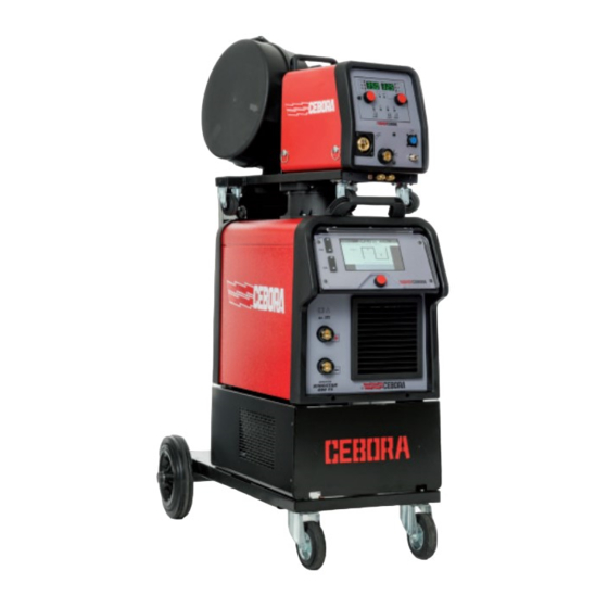
KINGSTAR 400 TS
Cebora KINGSTAR 400 TS Manuales
Manuales y guías de usuario para Cebora KINGSTAR 400 TS. Tenemos
3
Cebora KINGSTAR 400 TS manuales disponible para descarga gratuita en PDF: Manual De Instrucciones, Manual De Servicio
Cebora KINGSTAR 400 TS Manual De Servicio (176 páginas)
Marca:
Cebora
| Categoría:
Generadores
| Tamaño: 8.53 MB
Tabla de contenido
Italiano
2
Tabla de Contenido
2
1 Informazioni Generali
5
Introduzione
5
Avvertenze Generali
5
Informazioni Sulla Sicurezza
5
Compatibilità Elettromagnetica
5
2 Descrizione Sistema
6
Introduzione
6
Specifiche Tecniche
6
Descrizione Generatori KINGSTAR400TS, KINGSTAR 520TS
6
Gruppo DI Raffreddamento GRV12 (Opzionale) Art. 1683
9
Descizione Carrello Trainafilo
9
Aggiornamento Software
11
Chiavetta USB (USB Memory Stick)
11
3 Manutenzione
12
Ispezione Periodica, Pulizia
12
Attacchi E Connettori Sistema DI Saldatura
12
Comandi E Segnalazioni Pannello DI Controllo
13
Sequenze Operative
13
Funzionamento Sistema DI Saldatura
14
Funzionamento MIG
14
Funzionamento Regolare
16
Funzionamento TIG
16
Funzionamento MMA
18
Ricerca Guasti
19
Il Generatore Non si Accende, Pannello Controllo E Pannello Carrello Spenti
19
Verifica Funzionamento Ventilatore (21)
24
Il Pannello DI Controllo Non Indica Valori Corretti
24
Il Pulsante DI Start Non Provoca Alcun Effetto
26
Alcuni Comandi da Connettore E Non Funzionano
27
Non Esce Il Gas Dalla Torcia
27
Test Elettrovalvola
27
Sistema Alimentato, Non Funziona Il Motore Trainafilo
28
Non si Accende L'arco (Manca Tensione al Secondario Trasformatore (53))
29
Test Comando Driver Igbt
29
Test Corrente al Secondario del Trasformatore
31
Test Rlem Su Scheda Micro
31
Tensione D'uscita a Vuoto Non Corretta
31
Accensione Dell'arco Difficoltoso, L'arco si Spegne Subito Dopo L'innesco
32
In MIG, la Qualità Della Saldatura Non È Soddisfacente
32
Al Rilascio del Pulsante DI Star, Il Filo si Attacca al Pezzo da Saldare
32
TIG Arco Instabile, Saldatura Irregolare
33
In MMA Qualità Della Saldatura Non Soddisfacente
34
Gruppo Raffreddamento Non Funziona Correttamente (Opzionale)
34
Codici Errore
36
03 - Errore Generico Su Scheda Slave
36
04 - Errore Su Database
36
06 - Errore DI Comunicazione Rilevato da Scheda Pannello Master (70)
36
07 - Errore DI Comunicazione Su Can Bus, Rilevato da Scheda Master (70)
37
09 - Errore DI Comunicazione Rilevato da una Scheda Slave
37
10 - Mancanza Tensione E Corrente All'uscita
37
11 - Accensione con Carico Già Collegato
37
14 - Errore Tensione DI Alimentazione Su Scheda Micro (37)
37
20 - Assenza Segnale DI Interlock
37
22 - Errore Lettura Chiave Hardware
38
23 - Perdite Sul Collegamento DI Terra (PE Leakage)
38
25 - Anomalia Nel Bus FPGA DI Scheda Micro (62)
38
30 - Verifica Della Soglia Minima DI Corrente
38
42 - Errore Nel Segnale Encoder Motore (208)
39
53 - Start Premuto All'accensione O al Ripristino Per Sovratemperatura
39
54 - Corrente Diversa da Zero in Cortocircuito All'avvio
39
56 - Durata Eccessiva del Corto Circuito All'uscita
40
57 - Corrente del Motore Trainafilo (208) Eccessiva
40
58 - Errore DI Allineamento Versioni del Software O Errore Durante Fase DI Aggiornamento
40
60 - Corrente Media al DI Sopra del Limite Massimo Per Troppo Tempo
41
63 - Tensione DI Rete Non Corretta (Mancanza Fase)
41
73 - "Overtemperature Secondario". Temperatura del Gruppo Diodi (27)
41
74 - "Overtemperature Primario". Temperatura del Gruppo IGBT (48)
41
75 - "Pressione Liquido Raffreddamento Troppo Bassa" Sul Display LCD
42
76 - "Gruppo DI Raffreddamento Non Connesso" Sul Display LCD
42
78 - "Gas LO" Pressione del Gas Bassa
42
79 - "Gas HI" Pressione del Gas Alta
42
80 - "Open" Carter Gruppo Trainafilo Aperto
42
84 - "QC" Lampeggiante Su Pannello H. Controllo DI Qualità Fallito
42
85- "USB" Su Pannello H, Errore Durante L'aggiornamento del Firmware
42
90 - "Rob" CNC (Robot) in Emergenza Oppure Spento
42
91 - "STI" Filo Incollato
43
92 - "End" Filo Terminato
43
94 - "LOG" Datalogger Non Connesso
43
95 - "MAS" Maschera Bluetooth Non Connessa
43
97 - "CLI EC" Cavetto DI Misura Della Tensione Non Collegato
43
98 - "ITO" Arco Non Acceso Entri Il Tempo Prestabilito
44
99 - "OFF" . Tensione DI Rete Non Corretta ( Spegnimento Macchina )
44
5 Schemi Elettrici E Disegni Topografici
45
Scheda Potenza (48), Cod. 5602393 Per Art 372.00
46
Disegno Topografico
46
Tabella Connettori
46
Scheda Potenza (48), Cod. 5602471 Per Art 374.00
47
Tabella Connettori
47
4 Elenco Componenti
45
Disegno Esploso Generatore Art. 372.00
45
Tabella Componenti Generatore Art. 372.00
45
Disegno Esploso Generatore Art. 374.00
45
Tabella Componenti Generatore Art. 374.00
45
Disegno Esploso Carrello Trainafilo
45
Tabella Componenti Carrello Trainafilo
45
Disegno Esploso Gruppo Raffreddamento GRV12, Art. 1683.00
45
Tabella Componenti Gruppo Raffreddamento GRV12, Art. 1683.00
45
Scheda Micro (37), Cod. 5605218 Per Art. 372.00 E 5605197 Per Art. 374
48
Tabella Connettori
48
Scheda Pannello (70), Cod. 5605886 Per Art.372.00 E 5605887 Per Art.374.00
49
Tabella Connettori
49
Scheda Alimentatore Pannello Master (72), Cod. 5602576
50
Tabella Connettori
50
Scheda Alimentatore Carrello (42), Cod. 5602580
51
Tabella Connettori
51
Scheda Precarica Filtro Rete (39), 5602460 (Art.374) E 5602472 (Art.372)
52
Tabella Connettori
52
Scheda Controllo Motore (222), Cod. 5605217
53
Tabella Connettori
53
Scheda Pannello Carrello (212), Cod. 5605216
54
Tabella Connettori
54
Scheda Connettore (219), Cod. 5602599
54
6 Testing an Isotop Diode Module
55
Check for Shorted Diode
55
Check for Good Diode
55
English
57
1 General Information
60
Introduction
60
General Warnings
60
Safety Information
60
Electromagnetic Compatibility
60
2 Description of the System
61
Introduction
61
Technical Specifications
61
Power Source Description KINGSTAR400TS, KINGSTAR 520TS
61
Cooling Unit GRV12 (Optional) Item no 1683
64
Description of Wire Feed Unit
64
Software Update
66
USB Memory Stick
66
3 Maintenance
67
Periodic Inspection, Cleaning
67
Welding System Attachments and Connectors
67
Control Panel Controls and Signals of
68
Automatic Sequences
68
Operation of the Welding System
69
MIG Operation
69
Normal Operation
71
TIG Operation
71
MMA Operation
73
Troubleshooting
74
The Power Source Does Not Start, Control Panel off
74
Check Operation of Fan (21)
80
The Control Panel Does Not Indicate Correct Values
80
The START Button Produces no Effect
82
Some Commands from Connector E Not Operating
83
No Gas Flows from the Torch
83
Testing Solenoid
83
System Powered, Wire Feed Motor Not Working
84
The Arc Does Not Strike (no Voltage to the Secondary Winding of Transformer (53))
85
No Load Output Voltage Incorrect
88
Difficulty Striking the Arc, the Arc Turns off Immediately after Striking
88
In MIG Mode, Welding Quality Is Not Satisfactory
88
When the Start Button Is Released, the Wire Attaches to the Workpiece to be Welded
89
TIG Unstable Arc, Irregular Welding
89
In MMA Mode the Welding Quality Is Not Satisfactory
90
The Cooling Unit Is Not Working Properly (Option)
90
Error Codes
92
03 - Generic Error on Slave Board
92
04 - Error on Database
92
06 -Communication Error Detected by Master Panel Board (70)
92
07 -Communication Error in CAN-BUS Detected by Master Panel Board (70)
93
09 - Communication Error Detected by One Slave Board
93
10 - no Voltage or Current at Output
93
11 - Start-Up with Load Already Connected
93
14 - Microprocessor Power Voltage Error on the Microswitch Board (37)
93
20 - no Interlock Signal
93
22 -Hardware Key Reading Error
94
23 - Earth Connection Leakage (PE Leakage)
94
25 - Anomaly in the FPGA Bus of Microswitch Board (62)
94
30 - Checking Minimum Current Threshold
94
42 - Error in Motor Encoder Signal (208)
95
53 - Start Button Pressed at Power up or During Reset Due to Overtemperature
95
54 - Current Other than Zero Short-Circuited at Start-Up
95
56 - Excessive Duration of Short-Circuit at Output
96
57 - Excessive Current in Wire Feed Motor (208)
96
58 - Software Version Alignment Error or Error During Update
97
60 - Average Current above Maximum Limit for too Long
97
63 - Incorrect Mains Voltage (no Phase)
97
73 - "Secondary Winding Overtemperature". Temperature of Diode Assembly (27)
97
74 - "Primary Winding Overtemperature". Temperature of IGBT Assembly (48)
97
75 - "Coolant Pressure too Low" on the LCD Display
98
76 - "Cooling Unit Not Connected" on the LCD Display
98
78 - "Gas LO" Low Gas Pressure
98
79 - "Gas HI" High Gas Pressure
98
80 - "Open" Wire Feed Unit Casing Open
98
84 - "QC" Flashing on Panel H. Quality Control Failed
98
85- "USB" on Panel H, Error During Firmware Update
99
90 - "Rob" CNC (Robot) in Emergency Status or off
99
91 - "STI" Wire Stuck
99
92 - "End" Wire Ended
99
94 - "LOG" Datalogger Not Connected
99
95 - "MAS" Bluetooth Mask Not Connected
99
97 - "CLI EC" Voltage Measurement Cable Not Connected
99
98 - "ITO" Arc Not on Within the Pre-Established Time
101
99 - "OFF". Incorrect Mains Voltage Value (Machine Off)
101
4 Components List
102
Exploded View of Power Source Item no 372.00
102
Component Table for Power Source Item no 372.00
102
Exploded View of Power Source Item no 374.00
102
Component Table for Power Source Item no 374.00
102
Exploded View Drawing of Wire Feed Unit
102
Table Showing Wire Feed Unit Components
102
Exploded View of Cooling Unit GRV12, Item no 1683.00
102
Component Table for Cooling Unit GRV12, Item no 1683.00
102
5 Wiring Diagrams and Topographical Drawings
102
Power Board (48), Code 5602393 for Item no 372.00
103
Topographical Drawing
103
Connector Table
103
Power Board (48), Code 5602471 for Item no 374.00
104
Connector Table
104
Connector Table
105
Panel Board (70), Code 5605886 Per Item no 372.00 and 5605887 for Item no 374.00
107
Connector Table
107
Master Panel Power Board (72), Code 5602576
108
Connector Table
108
Wire Feed Unit Power Board (42), Code 5602580
109
Connector Table
109
Mains Filter Precharge Board (39), 5602460 (Item no 374) and 5602472 (Item no 372)
110
Connector Table
110
Motor Control Board (222), Code 5605217
111
Connector Table
111
Wire Feed Unit (212), Code 5605216
112
Connector Table
112
Connector Board (219), Code 5602599
112
6 Testing an Isotop Diode Module
113
Check for Shorted Diode
113
Check for Good Diode
113
GENERADOR Art
114
Español
115
1 Información General
118
Introducción
118
Advertecias Generales
118
Información sobre la Seguridad
118
Compatibilidad Electromagnética
118
2 Descripción del Sistema
119
Introducción
119
Especificaciones Técnicas
119
Descripción Generadores KINGSTAR400TS, KINGSTAR 520TS
119
Equipo de Enfriamiento GRV12 (Opcional) Art. 1683
122
Descripción Carro Arrastrahilo
122
Actualización Software
124
Lápiz USB (USB Memory Stick)
124
3 Mantenimiento
125
Inspección Periódica, Limpieza
125
Tomas y Conectores del Sistema de Soldadura
125
Mandos y Señalizaciones en el Tablero de Control
126
Secuencias Operativas
126
Funcionamiento del Sistema de Soldadura
127
Funcionamiento MIG
127
Funcionamiento Normal
129
Funcionamiento TIG
129
Funcionamiento MMA
131
Búsqueda de Averías
132
El Generador no Se Enciende, Panel de Control y Panel Carro Apagados
132
Control Funcionamiento Ventilador (21)
138
El Panel de Control no Presenta Valores Correctos
138
Control Versión del Software
138
Test de Comunicación Can-Bus
139
Test Mandos y Configuración Parámetros
140
El Pulsador de Encendido no Provoca Ningún Efecto
140
Algunos Mandos Procedentes del Conector E no Funcionan
141
Test Señales del Exterior
141
No Sale Gas de la Antorcha
142
Test Electroválvula
142
Sistema Alimentado, no Funciona el Motor Arrastrahilo
142
No Se Enciende el Arco, Falta Tensión en el Secundario del Transformador (53)
144
Test Alimentación de Potencia
144
Test Circuitos Driver Igbt
145
Test Alimentación Transductor de Corriente
146
Test Transductor de Corriente
146
Test Corriente en Secundario del Transformador
146
Tensión de Salida en Vacío Incorrecta
147
Test Tensión de Salida en Vacío
147
Encendido del Arco Dificultoso; el Arco Se Apaga Inmediatamente Después del Cebado
147
En MIG, la Calidad de la Soldadura no es Satisfactoria
147
Al Soltar el Pulsador de Start, el Hilo Se Pega a la Pieza por Soldar
148
Test Frenado Motor Arrastrahilo
148
TIG Arco Inestable, Soldadura Irregular
149
En MMA la Calidad de la Soldadura no es Satisfactoria
150
El Equipo de Enfriamiento no Funciona Correctamente (Opcional)
150
Códigos de Error
152
03 - Error Genérico en Tarjeta Slave
152
04 - Error en Base de Datos
152
06 - Error de Comunicación Detectado por Tarjeta Panel Master (70)
153
07 - Error de Comunicación en CAN Bus, Detectado por Tarjeta Master (70)
154
09 - Error de Comunicación Detectado por una Tarjeta Slave
154
10 - Falta Tensión y Corriente de Salida
154
11 - Encendido con Carga Ya Conectada
154
14 - Error Tensión de Alimentación en Tarjeta Micro (37)
154
20 - Ausencia Señal de "Interlock
154
22 - Error de Lectura Llave Hardware
155
23 - Pérdidas en la Conexión de Tierra (PE Leakage)
155
25 - Anomalía en el Bus FPGA de Tarjeta Micro (62)
155
Control del Umbral Mínimo de Corriente
156
42 - Error Señal Encoder Motor (208)
156
53 - Start Presionado al Encendido O Durante la Reanudación tras Sobretemperatura
156
54 - Corriente Diferente de Cero en Cortocircuito Durante la Puesta en Marcha
156
56 - Duración Excesiva del Cortocircuito en la Salida
157
57 - Corriente del Motor Arrastrahilo (208) Excesiva
157
Actualización
158
60 - Corriente Media por Encima del Límite Máximo Durante Demasiado Tiempo
158
63 - Tensión de Red Incorrecta (Falta Fase)
158
73 - "Sobretemperatura Secundario". Temperatura de la Unidad Diodos (27)
159
74 - "Sobretemperatura Primario". Temperatura de la Unidad IGBT (48)
159
75 - "Presión Líquido de Enfriamiento Demasiado Baja" en el Display LCD
159
76 - "Equipo de Enfriamiento no Conectado" en el Display LCD
159
78 - "GAS LO" Baja Presión del Gas
159
79 - "GAS HI" Alta Presión del Gas
159
80 - "Open" Cárter Unidad Arrastrahilo Abierta
160
84 - "QC" Centelleante en el Display H. Control de Calidad Fallido
160
85- "USB" en Display H, Error Durante la Actualización del Firmware
160
90 - "Rob" CNC (Robot) en Emergencia O Apagado
160
91 - "STI" Cable Pegado
160
92 - "End" Hilo Agotado
160
94 - "LOG" Datalogger no Conectado
160
95 - "MAS" Máscara Bluetooth no Conectada
161
97 - "CLI EC" Cable de Medición de la Tensión no Conectado
161
98 - "ITO" Arco no Encendido dentro del Tiempo Prestablecido
162
99 - "OFF" . Tensión de Red Incorrecta (Apagado de la Máquina)
162
4 Lista de Componentes
163
Dibujo de Despiece del Generador Art. 372.00
163
Tabla de Componentes Generador Art. 372.00
163
Dibujo de Despiece del Generador Art. 374.00
163
Tabla de Componentes Generador Art. 374.00
163
Dibujo de Despiece Carro Arrastrahilo
163
Tabla de Componentes Carro Arrastrahilo
163
Dibujo de Despiece Equipo de Enfriamiento GRV12, Art. 1683.00
163
Tabla de Componentes Equipo de Enfriamiento GRV12, Art. 1683.00
163
5 Esquemas Eléctricos y Dibujos Topográficos
163
Tarjeta de Potencia (48), CóD. 5602393 para Art. 372.00
164
Tabla Conectores
164
Tarjeta de Potencia (48), CóD. 5602471 para Art. 374.00
165
Tabla Conectores
165
Tarjeta Micro (37), CóD. 5605218 para Art. 372.00 y 5605197 para Art. 374
166
Tabla Conectores
166
Tarjeta Panel (70), CóD. 5605886 para Art. 372.00 y 5605887 para Art. 374.00
167
Tabla Conectores
167
Tarjeta Alimentador Panel Master (72), CóD. 5602576
168
Tabla Conectores
168
Tarjeta Alimentador Carro (42), CóD. 5602580
169
Tabla Conectores
169
Tarjeta Precarga Filtro Red (39), 5602460 (Art. 374) y 5602472 (Art. 372)
170
Tabla Conectores
170
Tarjeta Control Motor (222), CóD. 5605217
171
Tabla Conectores
171
Tarjeta Panel Carro (212), CóD. 5605216
172
Tabla Conectores
172
Tarjeta Conector (219), CóD. 5602599
172
6 Testing an Isotop Diode Module
173
Check for Shorted Diode
173
Check for Good Diode
173
Publicidad
Cebora KINGSTAR 400 TS Manual De Instrucciones (164 páginas)
Marca:
Cebora
| Categoría:
Sistemas de Soldadura
| Tamaño: 7.69 MB
Tabla de contenido
Italiano
2
Tabla de Contenido
2
Simbologia
5
Avvertenze
5
Targa Delle Avvertenze
6
Descrizione Generali
7
Spiegazione Dati Targa
7
Installazione
8
Collegamento Alla Rete
9
Messa in Opera E Installazione
9
Sollevamento E Trasporto
9
Installazione Generatore E Carrello
10
Descrizione del Generatore
12
Descrizione del Carrello
13
Descrizione Pannello Carrello
14
Descrizione Connettore Pannello Carrello Manuale
15
Descrizione Connettori Pannello Posteriore Generatore
16
Descrizione del Display
16
Interfaccia Gruppo DI Raffreddamento
16
Navigazione All'interno DI una Generica Schermata
18
Saldatura Mig
19
Collegamento Generatore-Carrello Trainafilo
19
Selezione Della Curva Sinergica
19
Descrizione Processo DI Saldatura
20
Modalità DI Partenza
21
Modalità SPOT
22
Impostazione Parametri DI Saldatura
23
Saldatura Tig DC
25
Modalità DOPPIO LIVELLO
23
Modalità DI Partenza
25
Selezione Processo DI Saldatura
25
Accensione Lift a Contatto
26
Modalità DI Innesco Arco
26
Tabella Regolazione Parametri Tig
26
Menù Pulsazione
27
Tig DC Apc
28
Tig DC Xp
28
Saldatura Mma
29
Parametri Processo Mma
29
Altre Funzioni del Pannello
30
Processo Mma DC
29
Cancellare un JOB
30
Gestione Job
30
Memorizzare un JOB DI Saldatura
30
Modificare Un Job
30
Consenti Regolazione DI un JOB
31
Copiare un JOB
31
Dettagli JOB
31
Saldare con un JOB
31
Menù Accessori
32
Menù Stato del Generatore
32
Salvataggio E Caricamento Singolo JOB da USB
32
Gruppo DI Raffreddamento
33
Push-Pull Torch
33
Push-Pull Torch Custom
33
Welding Mask
33
Max Inching
34
Push-Pull Cabration
34
Push-Pull Force
34
Torch Calibration
34
Controllo Qualità
35
Gas Regulation Kit
35
Impostazione Orologio, Lingua
35
Menù Impostazioni
35
Potentiometer Input
35
Production Mode
35
Gestione Utenti
36
Gestione USB
38
Funzionalità Avanzate
41
Impostazioni LAN
41
Barra DI Stato
42
Nome Generatore E Impianto
42
Ripristino Impostazioni DI Fabbrica
42
Menù Info
43
Webapp
44
Configurazione Robot
45
Descrizione del Sistema
46
Procedura DI Connessione
47
Connettori Posteriori Per Interfaccia Robot Ed Accessori
48
Settaggio Dip Switch E Terminazioni
48
Connettore CN1 - 10 Poli Femmina
49
Connettore CN2 - 7 Poli Femmina
49
Connettore CN3 - 7 Poli Femmina
50
Connettore CN4 - 10 Poli Femmina
50
CN6- Connettore Comandi SRS
51
CN7- Connettore Controllo SRS
51
Parametri DI Configurazione Interfaccia Robot
51
Quality Control
51
Dati Tecnici
52
Codici Errore
53
English
56
Important
58
Symbols
59
Warnings
59
Warning Plate
60
General Description
61
Explanation of Plate Data
61
Installation
62
Installation and Start up
63
Lifting and Transport
63
Mains Connection
63
Installing Power Source and Wire Feeder
64
Power Source Description
66
Wire Feeder Description
67
Wire Feeder Panel Description
68
Manual Wire Feeder Panel Connector Description
69
Cooling Unit Interface
70
Description of Display
70
Power Source Rear Panel Connector Description
70
Navigation Within a General Screen
72
Mig Welding
73
Power Source-Wire Feeder Connection
73
Selecting the Synergistic Curve
73
Description of the Welding Process
74
Start Mode
75
SPOT Mode
76
DOUBLE LEVEL Mode
77
Setting Welding Parameters
77
Tig DC Welding
79
Select Welding Process
79
Start Mode
79
Arc Striking Modes
80
Lift Contact Ignition
80
Tig Parameter Settings Table
80
Pulse Menu
81
Tig DC Apc
82
Tig DC Xp
82
Mma Welding
83
Mma DC Process
83
Mma Process Parameters
83
Other Panel Functions
84
Deleting a JOB
84
Job Management
84
Modifying a JOB
84
Saving a Welding JOB
84
Allow Adjustment of a JOB
85
Copying a JOB
85
JOB Details
85
Welding with a JOB
85
Accessories Menu
86
Power Source Status Menu
86
Saving and Loading an Individual JOB from a USB Drive
86
Cooling Unit
87
Push-Pull Torch
87
Push-Pull Torch Custom
87
Welding Mask
87
Max Inching
88
Push-Pull Calibration
88
Push-Pull Force
88
Torch Calibration
88
Gas Regulation Kit
89
Input Potentiometer
89
Production Mode
89
Quality Control
89
Setting the Clock, Language
89
Settings Menu
89
User Management
90
ADVANCED Mode
92
USB Management
92
Advanced Functionalities
95
LAN Setup
95
Name of Power Source and System
96
Restore Factory Setup
96
Status Bar
96
Info Menu
97
Webapp
98
Robot Configuration
99
Description of the System
100
Connection Procedure
101
Dip Switch and Terminal Settings
102
Rear Connectors for Robot Interface and Accessories
102
Connector CN1 - 10 Pin Female
103
Connector CN2 - 7 Pin Female
103
Connector CN3 - 7 Pin Female
104
Connector CN4 - 10 Pin Female
104
CN6- SRS Control Connector
105
CN7- SRS Control Connector
105
Quality Control
105
Robot Interface Configuration Parameters
105
Technical Specifications
106
Error Codes
107
Español
110
Simbología
113
Prudencia
113
Indicación
113
Advertencias
113
Placa de las Advertencias
114
Descripciones Generales
115
Explicación Datos de Placa
115
Instalación
116
Colocación E Instalación
117
Conexión a la Red
117
Potencia Motogenerador Necesaria
117
Elevación y Transporte
117
Instalación Generador y Carro
118
Descripción del Generador
120
Descripción del Carro
121
Descripción Panel Carro
122
Descripción Conector Panel Carro Manual
123
Descripción Conectores Panel Trasero Generador
124
Descripción del Display
124
Interfaz Equipo de Refrigeración
124
Navegación en una Pantalla Genérica
126
Soldadura Mig
127
Conexión Generador - Carro Arrastrahilo
127
Selección de la Curva Sinérgica
127
Descripción del Proceso de Soldadura
128
Modalidad de Arranque
129
Modalidad SPOT
130
Modalidad DOBLE NIVEL
131
Regulación Parámetros de Soldadura
131
Soldadura Tig DC
133
Modalidad de Arranque
133
Selección del Proceso de Soldadura
133
Encendido Lift por Contacto
134
Modalidad de Cebado Arco
134
Tabla Regulación Parámetros Tig
134
Menú Pulsación
135
Tig DC Apc
136
Tig DC Xp
136
Soldadura Mma
137
Parámetros Proceso Mma
137
Otras Funciones del Panel
138
Proceso Mma DC
137
Eliminar un JOB
138
Gestión Job
138
Memorizar un JOB de Soldadura
138
Modificar Un Job
138
Copiar un JOB
139
Detalles JOB
139
Posibilidad de Regulación de un JOB
139
Soldar con un JOB
139
Memorizar y Cargar un JOB de Soporte USB
140
Menú Accesorios
140
Menú Estado del Generador
140
Equipo de Refrigeración
141
Push-Pull Torch
141
Push-Pull Torch Custom
141
Welding Mask
141
Max Inching
142
Push-Pull Cabration
142
Push-Pull Force
142
Torch Calibration
142
Configuración Reloj, Idioma
143
Control de Calidad
143
Gas Regulation Kit
143
Menú de Configuración
143
Potentiometer Input
143
Production Mode
143
Gestión Usuarios
144
Funciones Controladas
145
Procedimiento de Recuperación del PIN
146
Modalidad ADVANCED
146
Gestión USB
146
Configuración LAN
149
Funciones Avanzadas
149
Barra de Estado
150
Nombre Generador E Instalación
150
Restablecimiento Configuración de Fábrica
150
Menú Info
151
Webapp
152
Configuración Robot
153
Descripción del Sistema
154
Posición Descripción
154
Procedimiento de Conexión
155
Conectores Posteriores para Interfaz Robot y Accesorios
156
Configuración Dip Switch y Terminales
156
Conector CN1 - 10 Polos Hembra
157
Conector CN2 - 7 Polos Hembra
157
Conector CN3 - 7 Polos Hembra
158
Conector CN4 - 10 Polos Hembra
158
CN6 - Conector Mandos SRS
159
CN7 - Conector Control SRS
159
Parámetros de Configuración Interfaz Robot
159
Quality Control
159
Datos Técnicos
160
Códigos de Error
161
Cebora KINGSTAR 400 TS Manual De Instrucciones (180 páginas)
Marca:
Cebora
| Categoría:
Sistemas de Soldadura
| Tamaño: 9.17 MB
Tabla de contenido
Tabla de Contenido
1
Targa Delle Avvertenze
2
Manuale DI Istruzioni Per Saldatrici a Filo
2
Compatibilità Elettromagnetica
2
Campi Elettromagnetici
2
Descrizioni Generali
3
Descrizione Dell'apparecchio
5
Descrizione del Pannello Comandi
7
Descrizione Delle Protezioni
8
Processo Mma
15
Saldatura Mig-Mag
16
Saldatura Tig
16
Saldatura Mma
16
Manutenzione Generatore
17
Electromagnetic Compatibility
18
Safety Precautions
18
Disposal of Electrical and Electronic Equipment
18
Warning Label
18
Instruction Manual for Wire Welding Machine
18
General Descriptions
19
Description of the Equipment
21
Control Panel Description
23
Mma Process
31
Mig/Mag Welding
31
Tig Welding
32
Mma Welding
32
Sicherheitsvorschriften
33
Elektromagnetische Felder
33
Elektromagnetische Verträglichkeit
33
Bedienungsanleitung für Lichtbogenschweissmaschinen
33
Allgemeine Beschreibung
34
Thermischer Schutz
35
Beschreibung des Geräts
37
Beschreibung der Steuertafel
39
Beschreibung der Schutzeinrichtungen
40
Mig-Mag-Schweissen
47
Wig-Schweissen
48
Mma-Schweissen
48
Plaquette des Avertissements
50
Compatibilite Electromagnetique
50
Manuel D'instructions pour Poste a Souder a Fil
50
Descriptions Generales
51
Mise en Place et Installation
51
Description de L'appareil
53
Description du Panneau de Commandes
56
Description des Protections
57
Mise en Place
57
Paramètres
60
ProcéDé Mma
63
Soudage Mig-Mag
64
Maintenance du Générateur
65
Soudage Tig
65
Soudage Mma
65
Precauciones de Seguridad
66
Manual de Instrucciones para Soldadora de Hilo
66
Descripciones Generales
67
Explicación de Los Datos Técnicos
67
Descripción del Aparato
69
Descripción del Panel de Mandos
71
Descripción del Equipo de Enfriamiento
72
Descripción de las Funciones Visualizadas en el Display
73
Accesorios
75
Parámetros
76
Configuraciones
76
Proceso Mma
79
Soldadura Mig/Mag
80
Soldadura Tig
81
Soldadura Mma
81
Mantenimiento del Generador
81
Precauções de Segurança
82
Chapa das Advertências
82
Manual de Instruções para Máquina de Soldar a Fio
82
Descrição Do Aparelho
86
Descrição Do Painel de Comandos
88
Acessórios
91
Configurações
92
Manutenção Do Gerador
97
Sähkömagneettinen Yhteensopivuus
98
Käyttöopas Mig-Hitsauskoneelle
98
Koneen Kuvaus
101
Tig-Hitsaus
112
Generel Beskrivelse
114
Ibrugtagning Og Installation
114
Beskrivelse Af Maskinen
116
Tig-Svejsning
128
Plaatje Met Waarschuwingen
129
INSTRUKTIONSMANUAL for SVEJSEAPPARAT TIL TRÅDSVEJSNING Side. 113 GEBRUIKSAANWIJZING VOOR MIG-LASMACHIN
129
Algemene Beschrijving
130
Inbedrijfstelling en Installatie
131
Beschrijving Van Het Apparaat
132
Beschrijving Van Het Bedieningspaneel
134
Beschrijving Van de Beveiligingen
135
Mig-Mag-Lassen
143
Onderhoud Generator
144
Instruktionsmanual För Trådsvets
145
Allmän Beskrivning
146
Inställningar
155
TIG-Process
155
Περιγραφη Τησ Συσκευησ
165
Συγκολληση Tig
176
Συγκολληση Mma
176
Publicidad
Publicidad
Productos relacionados
Cebora 452
Cebora 449.00
Cebora WIN TIG AC-DC 450T
Cebora 465.01
Cebora 476.50
Cebora KINGSTAR 520 TS
Cebora 408
Cebora 428.01
Cebora 428.02
Cebora 433
Cebora Categorias
Sistemas de Soldadura
Generadores
Accesorios de Soldaduras
Paneles de Control
Interfaces USB
Más Cebora manuales
Login
Entrar
O
Iniciar sesión con Facebook
Iniciar sesión con Google
Cargar el manual
Cargar desde el disco
Cargar desde la URL