Graco Mark X Manual Del Usuario
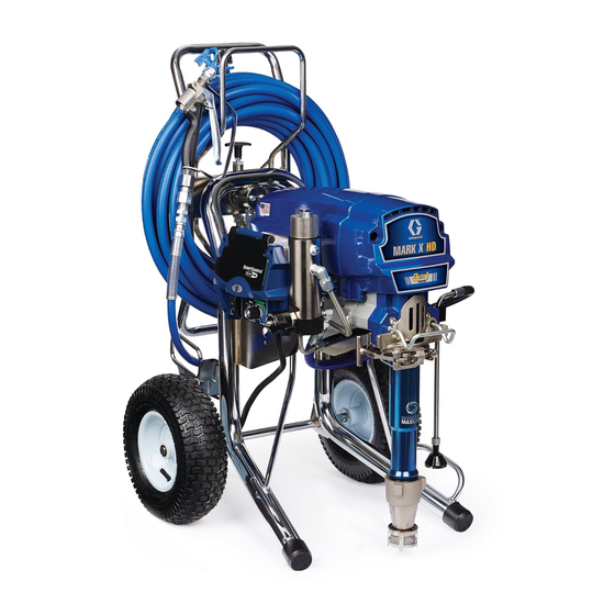
Pulverizador eléctrico, sin aire, para uso intensivo, para enyesados y pinturas, presión máxima de trabajo 228 bar 22,8 mpa, 3300 psi
Ocultar thumbs
Ver también para Mark X:
- Manual de instrucciones (86 páginas) ,
- Funcionamiento, piezas (88 páginas) ,
- Instrucciones importantes de seguridad (26 páginas)
Tabla de contenido
Publicidad
Enlaces rápidos
Instructions / Instructions / Instrucciones /
Istruzioni / Instructies
™
Mark X
- Heavy Duty Electrical Airless Sprayer of Plasters and Paints -
- Pulvérisateur électrique sans air pour usage intensif et pour enduits et peintures -
- Pulverizador eléctrico, sin aire, para uso intensivo, para enyesados y pinturas -
- Spruzzatore elettrico airless per usi gravosi per intonaci e vernici -
- Heavy-duty elektrisch airless spuittoestel voor pleister- en schilderwerk -
Models / Modèles / Modelos / Modelli / Modellen: 249627, 249628
228 bar (22,8 MPa, 3300 psi) Maximum Working Pressure
Pression de service maximum : 228 bars (22,8 MPa, 3300 psi)
Presión máxima de trabajo 228 bar (22,8 MPa, 3300 psi)
Pressione massima di esercizio 228 bar, 22,8 MPa (3300 psi)
Maximum werkdruk: 228 bar (22,8 MPa, 3300 psi)
Important Safety Instructions
Read all warnings and instructions in this manual.
Save these instructions.
Instructions de sécurité importantes
Lire toutes les mises en garde et instructions
de ce manuel. Sauvegarder ces instructions.
Instrucciones importantes de seguridad
Lea todas las advertencias e instrucciones
de este manual. Guarde las instrucciones.
Importanti istruzioni sulla sicurezza
Leggere tutte le avvertenze e le istruzioni contenute
in questo manuale. Conservarle.
Belangrijke veiligheidsinstructies
Lees alle waarschuwingen en instructies
in deze handleiding. Bewaar deze instructies.
309495
309277
309055
Graco Inc. P.O. Box 1441 Minneapolis, MN 55440-1441
Copyright 2006, Graco Inc. is registered to I.S. EN ISO 9001
311421E rev.g
ti7502a
Publicidad
Tabla de contenido

Manuales relacionados para Graco Mark X


Resumen de contenidos para Graco Mark X
- Página 1 Conservarle. Belangrijke veiligheidsinstructies Lees alle waarschuwingen en instructies in deze handleiding. Bewaar deze instructies. 309495 309277 309055 ti7502a Graco Inc. P.O. Box 1441 Minneapolis, MN 55440-1441 Copyright 2006, Graco Inc. is registered to I.S. EN ISO 9001...
-
Página 2: Tabla De Contenido
Table of Contents / Table des matières / Índice / Indice / Inhoudsopgave Warning ............3 Motor Replacement / Remplacement du moteur / Reemplazo del motor / Mise en garde . -
Página 3: Warning
Read fluid and solvent manufacturer’s warnings. For complete information about your material, request MSDS forms from distributor or retailer. • Check equipment daily. Repair or replace worn or damaged parts immediately with genuine Graco replacement parts only. •... - Página 4 Warning WARNING ELECTRIC SHOCK HAZARD Improper grounding, setup, or usage of the system can cause electric shock. • Turn off and disconnect power cord before servicing equipment. • Use only grounded electrical outlets. • Use only 3-wire extension cords. • Ensure ground prongs are intact on sprayer and extension cords.
-
Página 5: Mise En Garde
Pour plus d’informations sur votre produit, demandez la fiche de sécurité sur les produits à votre distributeur ou revendeur de produit. • Vérifier le matériel quotidiennement. Réparer ou remplacer immédiatement toutes les pièces usées ou endommagées uniquement par des pièces d’origine Graco. • Ne pas modifier cet équipement. •... - Página 6 Mise en garde MISE EN GARDE DANGER DE DÉCHARGE ÉLECTRIQUE Une mauvaise mise à la terre, un mauvais réglage ou une mauvaise utilisation du système peut provoquer une décharge électrique. • Mettre hors tension et débrancher le câble d’alimentation avant de procéder à un entretien du matériel. •...
-
Página 7: Advertencia
Para obtener información completa sobre su material, pida las hojas de MSDS a su distribuidor o detallista. • Revise el equipo a diario. Repare o cambie inmediatamente las piezas desgastadas o dañadas únicamente con piezas de repuesto originales de Graco. • No altere ni modifique el equipo. •... -
Página 8: Peligro De Descarga Eléctrica
Advertencia ADVERTENCIA PELIGRO DE DESCARGA ELÉCTRICA Una conexión a tierra, montaje o utilización incorrectos del sistema puede causar descargas eléctricas. • Apague y desconecte la alimentación eléctrica antes de desconectar el equipo. • Utilice únicamente tomas eléctricas conectadas a tierra. •... -
Página 9: Avvertenza
• Non alterare o modificare l’attrezzatura. • Utilizzare l’apparecchiatura solo per gli scopi previsti. Per informazioni, contattare il distributore Graco. • Disporre i flessibili e i cavi lontano da aree trafficate, spigoli vivi, parti in movimento e superfici calde. •... - Página 10 Avvertenza AVVERTENZA PERICOLO DI SCOSSE ELETTRICHE Il collegamento a terra non corretto, un’inizializzazione o un uso improprio del sistema può causare una scossa elettrica. • Disattivare e arrestare il cavo di alimentazione prima di eseguire la manutenzione dell’attrezzatura. • Utilizzare solo uscite elettriche con messa a terra. •...
-
Página 11: Waarschuwing
• Geen veranderingen of wijzigingen in de apparatuur aanbrengen. • De apparatuur alleen voor het beoogde doel gebruiken. Neem contact op met uw Graco-leverancier voor meer informatie. • Houd slangen en kabels uit de buurt van plaatsen waar gereden wordt, scherpe randen, bewegende onderdelen en hete oppervlakken. - Página 12 Waarschuwing WAARSCHUWING GEVAAR VOOR ELEKTRISCHE SCHOKKEN Slechte aarding, onjuiste installatie of onjuist gebruik van het systeem kan elektrische schokken veroorzaken. • Zet het toestel uit via de hoofdschakelaar en haal de stekker uit het stopcontact voordat u onderhoud gaat plegen aan de apparatuur. •...
-
Página 13: Grounding / Mise À La Terre / Conexión A Tierra / Messa A Terra / Aarding
Tutti i cavi per spruzzatori Graco Alimentazione Circuito Non alterare lo spinotto Inserire il cavo dello includono un filo di terra per a 230 V AC, 50/60 Hz, di terra né... - Página 14 Grounding / Mise à la terre / Conexión a tierra / Messa a terra / Aarding Use grounded metal pails Place pail on grounded Hold spray gun against Use 1,5 mm grounded for solvent and oil-based surface such as concrete grounded metal pail when extension cords, 30 m fluids.
-
Página 15: Operation / Fonctionnement / Funcionamiento / Funzionamento / Bediening
Operation / Fonctionnement / Funcionamiento / Funzionamento / Bediening Operation / Fonctionnement / Funcionamiento / Funzionamento / Bediening Component Identification / Identification des composants / Identificación de los componentes / Identificazione dei componenti / De onderdelen Note: Locate model and serial number tag on page 85, Ref 139 Remarque : le modèle et le numéro de série se trouvent sur l’étiquette montrée à... -
Página 16: Setup / Réglage / Puesta En Marcha / Configurazione / Opstellen
15 m. Conecte la manguera Instale el adaptador y la Instale la manguera flexible Apriete firmemente. sin aire Graco de 15 m manguera flexible de 3,6 m en la entrada de fluido de al pulverizador. al otro extremo de la la pistola de pulverización. - Página 17 Setup / Réglage / Puesta en marcha / Configurazione / Opstellen Approximative Fill Level / Niveau de remplissage approximatif / Nivel de llenado aproximado / Livello di riempimento approssimativo / Vulniveau (bij benadering) Remove inlet strainer and Fill throat packing nut with Turn power OFF.
- Página 18 Setup / Réglage / Puesta en marcha / Configurazione / Opstellen ti7506a Turn prime valve down. Place pump in grounded metal pail partially filled with flushing fluid. Attach ground wire to pail and to true earth ground, page 14. Do 1. - 5. of Startup to flush out storage oil shipped in sprayer. Use water to flush water-base paint and appropriate solvent to flush oil-base paint and storage oil.
-
Página 19: Startup / Démarrage / Puesta En Marcha / Avvio / Opstarten
Startup / Démarrage / Puesta en marcha / Avvio / Opstarten Startup / Démarrage / Puesta en marcha / Avvio / Opstarten ti7507a Turn pressure control Turn power ON. Increase pressure 1/2 to Turn prime valve horizontal. to lowest pressure. start motor and allow fluid Take spray gun trigger to circulate through drain... - Página 20 Startup / Démarrage / Puesta en marcha / Avvio / Opstarten ti4271a Hold gun against grounded Inspect for leaks. Do not stop leaks Place pump in material pail. Trigger gun again into flushing metal flushing pail. Trigger with hand or a rag! If leaks occur, pail until paint appears.
-
Página 21: Install Spray Tip
Startup / Démarrage / Puesta en marcha / Avvio / Opstarten Install Spray Tip Insert tip cylinder into guard Install OneSeal (curved Install assembled tip and Install appropriate tip (arrow points forward). side in) into housing. guard onto spray gun. for your material. -
Página 22: Spray
Startup / Démarrage / Puesta en marcha / Avvio / Opstarten heavy edges / bords trop chargés / extremos densos / bordi pesanti / zware randen Spray Clear Clog 1 Spray test pattern. Adjust pressure 2 Hold gun perpendicular, 10-12 in. 1 Release trigger, put safety ON. -
Página 23: Digital Tracking System (Dts) / Système De Suivi Numérique (Dts) / Sistema De Control Digital (Dts) / Sistema Di Controllo Digitale (Dts) / Digitaal Tracking Systeem (Dts)
Digital Tracking System (DTS) / Système de suivi numérique (DTS) / Sistema de control digital (DTS) / Sistema di controllo digitale (DTS) / Digitaal Tracking Systeem (DTS) Digital Tracking System (DTS) / Système de suivi numérique (DTS) / Sistema de control digital (DTS) / Sistema di controllo digitale (DTS) / Digitaal Tracking Systeem (DTS) Operation Main Menu Change Display Units... - Página 24 Digital Tracking System (DTS) / Système de suivi numérique (DTS) / Sistema de control digital (DTS) / Sistema di controllo digitale (DTS) / Digitaal Tracking Systeem (DTS) OR / OU / O / OPPURE / Operation Main Menu Short press DTS button to move Press and hold to reset to zero, Short press DTS button to return to Job Liters x 10 (or Gallons).
-
Página 25: Secondary Menu
Appuyer sur le bouton DTS Le pulvérisateur affiche Appuyer brièvement sur page 27, points 1 – 4 si cela et mettre le bouton brièvement (p. ex. MARK X). le bouton DTS. MOTEUR n’a pas encore été fait. marche-arrêt sur MARCHE. NUMÉRO DE SÉRIE défile, MARCHE défile. - Página 26 Digital Tracking System (DTS) / Système de suivi numérique (DTS) / Sistema de control digital (DTS) / Sistema di controllo digitale (DTS) / Digitaal Tracking Systeem (DTS) Secondary Menu Short press DTS button. Press and hold DTS button Short press to move to LAST ERROR scrolls to clear error code to zero.
-
Página 27: Pressure Relief / Décompression / Alivio De La Presión / Scaricare La Pressione / De Druk Ontlasten
Pressure Relief / Décompression / Alivio de la presión / Scaricare la pressione / De druk ontlasten Pressure Relief / Décompression / Alivio de la presión / Scaricare la pressione / De druk ontlasten Turn power OFF. Lock gun trigger safety. Turn pressure to lowest Put drain tube in pail. -
Página 28: Cleanup / Nettoyage / Limpieza / Pulizia / Reinigen
Cleanup / Nettoyage / Limpieza / Pulizia / Reinigen Cleanup / Nettoyage / Limpieza / Pulizia / Reinigen Do Pressure Relief, Note: Use water for water base Increase pressure to 1/2. Move gun to waste pail, steps 1- 4, page 27. material and appropriate solvent Hold gun against paint pail. - Página 29 Cleanup / Nettoyage / Limpieza / Pulizia / Reinigen Turn prime valve down Raise pump above flushing Close drain valve. Trigger Open prime valve. and allow flushing fluid to fluid and run sprayer for 15 gun into flushing pail to Unplug sprayer.
- Página 30 Cleanup / Nettoyage / Limpieza / Pulizia / Reinigen Pump Armor / Protection de pompe / Protección para bombas / Pump Armor / Pump Armor Remove filters from gun and sprayer, If flushing with water, flush again with Wipe sprayer, hose and gun with a rag if installed.
-
Página 31: Troubleshooting
Troubleshooting Troubleshooting Do Pressure Relief; page 27. Mechanical/Fluid Flow PROBLEM CAUSE SOLUTION Low or No Fluid/Pressure Output Spray tip worn. Follow Pressure Relief Procedure Warning, then replace tip. See your separate gun or tip manual. Switch 10/14A. Verify sprayer is connected to a 230V, 16A circuit. - Página 32 Troubleshooting Electrical Symptom: Sprayer does not run or stops running Relieve pressure; page 27. To avoid electrical shock or moving parts hazards when covers are removed for troubleshooting, wait • Plug sprayer into correct voltage, grounded outlet 30 seconds after unplugging power cord for stored electricity to dissipate.
- Página 33 Troubleshooting Electrical DIGITAL CONTROL BOARD INDICATION WHAT TO DO DISPLAY STATUS LIGHT Displays high Improper pressure Open prime valve. Connect a known good transducer in pressure when signal to control place of the sprayer transducer. Set sprayer ON. Replace prime valve is transducer If sprayer runs.
- Página 34 Troubleshooting Electrical DIGITAL CONTROL BOARD INDICATION WHAT TO DO DISPLAY STATUS LIGHT E=05 Blinks 5 x repeatedly Possible locked Check motor wiring connections. pump or drive. May Check for locked or frozen pump or drive train. be motor connection If all motor wiring connections are OK and pump/drive train or wiring error are not locked up, replace control board, then motor.
-
Página 35: Guide De Dépannage
Guide de dépannage Guide de dépannage Effectuer la Décompression, page 27. Mécanique/débit produit PROBLÈME CAUSE SOLUTION Pas de produit ou basse pression en sortie Buse de pulvérisation usagée. Toujours respecter la Mise en garde de la procédure de décompression, remplacer ensuite la buse. - Página 36 Guide de dépannage Électrique Symptôme : le pulvérisateur ne fonctionne pas ou s’arrête Décompression, page 27. Pour éviter toute décharge électrique ou tout risque de blessure par des pièces mobiles quand les capots ont été ôtés pour dépannage, attendre 30 secondes après le débranchement du •...
- Página 37 Guide de dépannage Électrique AFFICHAGE LAMPE DE SIGNIFICATION INTERVENTION NUMERIQUE CONTRÔLE DE LA CARTE DE COMMANDE Affiche une Signal de pression Ouvrir la vanne d’amorçage. Brancher un capteur en état haute pression erroné transmis de marche à la place du capteur du pulvérisateur. Mettre quand la vanne à...
- Página 38 Guide de dépannage Électrique AFFICHEUR LAMPE DE SIGNIFICATION INTERVENTION NUMÉRIQUE CONTRÔLE DE LA CARTE DE COMMANDE E=05 Clignote 5 x de Pompe ou Contrôler le câblage moteur. façon répétée. transmission Vérifier si la pompe ou la transmission sont bloquées peut-être bloquées. ou gelées.
-
Página 39: Localización De Averías
Localización de averías Localización de averías Realice el Procedimiento de descompresión, página 27. Mecánico/Caudal de fluido PROBLEMA CAUSA SOLUCIÓN Salida de presión de fluido baja o inexistente Boquilla de pulverización gastada. Siga las indicaciones de la advertencia Procedimiento de descompresión y cambie la boquilla. -
Página 40: Indicación
Localización de averías Eléctrico Síntoma: El pulverizador no funciona o deja de funcionar Libere la presión, página 27. Para evitar el riesgo de descargas eléctricas o piezas en movimiento cuando se retiran las cubiertas para realizar la localización de averías, espere 30 segundos después •... - Página 41 Localización de averías Eléctrico PANTALLA INDICADOR DE INDICACIÓN QUÉ HACER DIGITAL ESTADO DE LA TARJETA DE CONTROL Muestra alta Señal de presión Abra la válvula de cebado. Reemplace el transductor presión cuando incorrecta al del pulverizador por uno en buen estado. Encienda la válvula de dispositivo de el pulverizador.
- Página 42 Localización de averías Eléctrico PANTALLA INDICADOR DE INDICACIÓN QUÉ HACER DIGITAL ESTADO DE LA TARJETA DE CONTROL E=05 Parpadea 5 veces Posible bloqueo de la Inspeccione las conexiones del cableado del motor. reiteradamente bomba o el impulsor. Compruebe si la bomba o el tren de accionamiento está Podría haber un error bloqueado o congelado.
-
Página 43: Individuazione E Correzione Malfunzionamenti
Individuazione e correzione malfunzionamenti Individuazione e correzione malfunzionamenti Eseguire la decompressione, a pagina 27. Flusso meccanico/del fluido PROBLEMA CAUSA SOLUZIONE Nessuna o bassa emissione fluido/pressione Ugello consumato. Seguire gli avvertimenti per le procedure di decompressione e poi sostituire l’ugello. Fare riferimento al manuale specifico della pistola o dell’ugello Interruttore 10/14A. - Página 44 Individuazione e correzione malfunzionamenti Elettrico Sintomo: Lo spruzzatore non funziona o si arresta Fare sfogare la pressione; pagina 27. Per evitare shock elettrici o pericoli dovuti a parti in movimento quando si rimuovono le coperture per individuare i guasti, • Collegare lo spruzzatore a una presa collegata a terra, attendere 30 secondi dopo aver scollegato il cavo di di tensione corretta...
- Página 45 Individuazione e correzione malfunzionamenti Elettrico DISPLAY LUCE DI STATO INDICAZIONE CHE COSA FARE DIGITALE DELLA SCHEDA DI CONTROLLO Visualizza Segnale di pressione Aprire la valvola di adescamento. Collegare un trasduttore l’alta pressione non corretto al che si sa essere funzionante al posto del trasduttore dello quando la controllo spruzzatore.
- Página 46 Individuazione e correzione malfunzionamenti Elettrico DISPLAY LUCE DI STATO INDICAZIONE CHE COSA FARE DIGITALE DELLA SCHEDA DI CONTROLLO E=05 Lampeggia 5 volte Possibile pompa Controllare le connessioni dei fili del motore. ripetutamente o trasmissione Controllare un eventuale blocco o congelamento bloccata.
-
Página 47: Storingen Opsporen En Verhelpen
Storingen opsporen en verhelpen Storingen opsporen en verhelpen Voer de drukontlastingsprocedure uit; zie blz. 27. Mechanische/materiaalstroom PROBLEEM OORZAAK OPLOSSING Weinig of geen materiaal/drukuitvoer Versleten spuittip. Volg de Drukontlastingsprocedure en vervang dan de tip. Zie de afzonderlijke handleiding voor de tip of het pistool. Schakelaar 10/14A. - Página 48 Storingen opsporen en verhelpen Elektrisch Symptoom: Het spuitapparaat loopt niet of houdt op met werken Ontlast de druk; zie blz. 27. Om geen elektrische schok te krijgen of gevaar voor letsel door bewegende delen te voorkomen als de beschermkappen zijn verwijderd voor probleemoplossing, moet u 30 seconden •...
- Página 49 Storingen opsporen en verhelpen Elektrisch DIGITALE STATUSLAMPJE INDICATIE WAT TE DOEN DISPLAY BESTURINGSKAART Toont hoge Onjuist druksignaal Open de voorpompkraan. Sluit een drukomzetter waarvan druk als de naar de regelaar. u weet dat hij goed is aan in plaats van de omzetter van voorpompkraan het spuitapparaat.
- Página 50 Storingen opsporen en verhelpen Elektrisch DIGITALE STATUSLAMPJE INDICATIE WAT TE DOEN DISPLAY BESTURINGSKAART E=05 Knippert steeds 5 x in Mogelijk vastzittende Controleer de draadaansluitingen van de motor. successie pomp of aandrijving. Controleer of de pomp of de aandrijving is vastgelopen Kan een probleem zijn of vastgevroren.
-
Página 51: Repair / Réparation / Reparación / Riparazione / Repareren
Repair / Réparation / Reparación / Riparazione / Repareren Repair / Réparation / Reparación / Riparazione / Repareren Displacement Pump Replacement / Remplacement du bas de pompe / Sustitución de la base de bomba / Sostituzione del pompante / De verdringerpomp vervangen ti13934a Pump Removal Flush pump. - Página 52 Repair / Réparation / Reparación / Riparazione / Repareren Pump Removal Ratchet pump door forward. Twist latch u-bolt out of Place u-bolt on pump door Ratchet pump door forward. pump door recess. protrusion. Démontage de la pompe Manœuvrer le levier en Sortir l’étrier de son Placer l’étrier contre Manœuvrer le levier en...
- Página 53 Repair / Réparation / Reparación / Riparazione / Repareren Pump Removal Open pump door. 10 Pull out pump pin and place in pin holder. It is recommended that the check valve (32) berepaired at the same time as the pump. For check valve repair, see manual 313773.
-
Página 54: Pump Installation
Repair / Réparation / Reparación / Riparazione / Repareren Pump Installation Adjust piston rod with pin Push pump collar flush with Warning: If pump pin is not Slide pump into connecting holder to pull out piston rod. bearing housing ledge to be inserted properly, it could work rod. - Página 55 Repair / Réparation / Reparación / Riparazione / Repareren Pump Installation Close pump door and rotate latch into position. Do not tighten latch. Rotate pump to align with Tighten latch. paint hose. Connect paint hose and hand tighten to 8 N ·...
- Página 56 Ruotare il fermo del gancio Collegare il flessibile di Riempire la pompa con nella posizione di blocco. drenaggio allo spruzzatore. Graco TSL, fino a che il fluido scorre sopra la guarnizione. De pomp installeren Roteer de veervergrendeling Verbind de aftapslang aan Vul de pakkingmoer met in de vergrendelde stand.
-
Página 57: Drive And Bearing Housing Replacement / Remplacement Du Carter
Repair / Réparation / Reparación / Riparazione / Repareren Drive and Bearing Housing Replacement / Remplacement du carter d’entraînement et du corps de palier / Reemplazo del alojamiento del impulsor y del cojinete / Sostituzione della scatola della trasmissione e del cuscinetto / Het aandrijfhuis en het lagerhuis vervangen Drive and Bearing Housing Removal Warning: Do Pressure Relief,... - Página 58 Repair / Réparation / Reparación / Riparazione / Repareren Drive and Bearing Housing Removal Remove four screws and Remove six screws and pull washers and remove drive housing off motor. bearing housing and connecting rod. Dépose du carter d’entraînement et du corps de palier Enlever les quatre vis Enlever six vis et extraire et rondelles et déposer...
-
Página 59: Drive And Bearing Housing Installation
Repair / Réparation / Reparación / Riparazione / Repareren Drive and Bearing Housing Installation Make sure gear and thrust washers Push drive housing Install bearing housing Install front cover with are in place. Brush grease onto onto motor and install with four screws and four screws. - Página 60 Repair / Réparation / Reparación / Riparazione / Repareren Drive and Bearing Housing Installation Install shroud with Install pump; two screws. Displacement Pump Replacement, page 54. Installation du carter d’entraînement et du corps de palier Fixer le capotage à l’aide Monter la pompe;...
-
Página 61: Motor Replacement / Remplacement Du Moteur / Reemplazo Del Motor / Sostituzione Del Motore / De Motor Vervangen
Repair / Réparation / Reparación / Riparazione / Repareren Motor Replacement / Remplacement du moteur / Reemplazo del motor / Sostituzione del motore / De motor vervangen Motor Removal Warning: Do Pressure Relief; Remove pump; Displacement Remove drive housing Do Control Board Removal page 27. - Página 62 Repair / Réparation / Reparación / Riparazione / Repareren ti7218a Motor Removal Loosen two nuts on side Remove two screws and nuts near control. on side opposite control and Warning sharp edges! remove motor from cart frame. Push stain relief out of power bar plate and remove from motor wires.
-
Página 63: Motor Installation
Repair / Réparation / Reparación / Riparazione / Repareren ti7218a Motor Installation Slide new motor under Install two screws and nuts Do Control Board Install drive housing and bearing two screws in cart frame on motor side opposite Installation steps 5-21, housing: Drive and Bearing near control. - Página 64 Repair / Réparation / Reparación / Riparazione / Repareren Motor Installation Install pump; Displacement Pump Replacement, page 54. Installation du moteur Monter la pompe ; Changement de bas de pompe, page 54. Instalación del motor Instale la bomba; vea Sustitución de la base de bomba, en la página 54.
-
Página 65: Control Board Replacement / Remplacement De La Carte De Commande / Reemplazo De La Tarjeta De Control / Sostituzione Della Scheda Di Controllo / De Besturingskaart Vervangen
Repair / Réparation / Reparación / Riparazione / Repareren Control Board Replacement / Remplacement de la carte de commande / Reemplazo de la tarjeta de control / Sostituzione della scheda di controllo / De besturingskaart vervangen ti7561a Control Board Removal Warning: Do Pressure Relief;... - Página 66 Repair / Réparation / Reparación / Riparazione / Repareren ti7818b ti7582b ti12501a Control Board Removal Remove two bottom screws. Remove blue (NEUTRAL) Remove grounding screw Remove 10/14A switch Remove top two screws and black (LINE) connectors from power bar plate. connector from motor control and partially remove control from filter board.
- Página 67 Repair / Réparation / Reparación / Riparazione / Repareren ti11509a ti11511a ti7585a Control Board Removal Disconnect potentiometer Disconnect transducer Slide transducer grommet Disconnect motor connector from motor connector from motor out of control housing and connector from motor control board. control board.
- Página 68 Repair / Réparation / Reparación / Riparazione / Repareren ti11510b ti11507b ti11520a Control Board Removal Disconnect two coil connectors Disconnect motor resolver Disconnect motor two wire Remove motor shield from motor control board. power connector from connector from motor from sprayer. motor control board.
- Página 69 Repair / Réparation / Reparación / Riparazione / Repareren ti12482a ti12481a ti12483a Control Board Removal Remove paint hose from power Remove valve block from power Remove power bar plate from bar plate hydraulic fitting. bar plate. cart frame. Warning sharp edges! Remove motor grommet from power bar plate.
-
Página 70: Control Board Installation
26,0 N·m (200 - 230 in-lb). De besturingskaart installeren Installeer de bewapenings- Reinig de o-ringzitting in Installeer het ventielblok Installeer de verfslang plaat uit de Mark X 220V het ventielblok. Breng vet op de bewapeningsplaat. op de hydraulische fitting besturingskaartherstelset aan op de o-ringzitting. - Página 71 Repair / Réparation / Reparación / Riparazione / Repareren ti11500a ti11507a Control Board Installation Insert motor and coil wires into Connect two coil connectors Connect motor two-wire motor grommet. Insert motor to motor control board. connector to motor control Warning sharp edges! grommet into power bar plate.
- Página 72 Repair / Réparation / Reparación / Riparazione / Repareren ti11510a ti12501a ti7585 Control Board Installation Connect motor resolver Connect motor connector Slide transducer grommet Install grounding screw connector to motor control to motor control board. into control housing. to power bar plate. Torque board.
- Página 73 Repair / Réparation / Reparación / Riparazione / Repareren ti7818b ti11511a ti7582b Control Board Installation Install 10/14A switch Install blue (NEUTRAL) Install control housing Connect transducer connector to motor and black (LINE) with two top screws and connector to motor control board.
- Página 74 Repair / Réparation / Reparación / Riparazione / Repareren ti7561a ti11509a Control Board Installation Connect potentiometer Install control panel Connect display connector Install cover with connector to motor control with two screws. to motor control board. four screws. board. Montage de la carte de commande Brancher le connecteur du Fixer le panneau de Brancher le connecteur...
- Página 75 Repair / Réparation / Reparación / Riparazione / Repareren ti11520a Control Board Installation Install motor shield Do StartUp; page 19, to on sprayer. verify correct installation. Montage de la carte de commande Remonter le fond de moteur Faire un démarrage ; sur le pulvérisateur.
-
Página 76: Pressure Adjust Potentiometer Replacement / Remplacement
Repair / Réparation / Reparación / Riparazione / Repareren Pressure Adjust Potentiometer Replacement / Remplacement du potentiomètre de réglage de pression / Reemplazo del potenciómetro de ajuste de la presión / Sostituzione del potenziometro di regolazione della pressione / De potentiometer van de drukafstelling vervangen Pressure Adjust Potentiometer Removal Warning: Do Pressure Relief;... - Página 77 Repair / Réparation / Reparación / Riparazione / Repareren Pressure Adjust Potentiometer Installation Install gasket, nut and Install pressure control knob: Connect potentiometer Install control panel with potentiometer on control panel. Check pressure control knob connector to motor control two screws. Install cover Torque nut to 3.38-3.95 N·m alignment to potentiometer board.
-
Página 78: Pressure Control Transducer Replacement / Remplacement Du Capteur De Pression / Reemplazo Del Transductor De Control De Presión / Sostituzione Del Trasduttore Del Controllo Di Pressione / De Omzetter Voor De Drukregeling Terug Zetten
Repair / Réparation / Reparación / Riparazione / Repareren Pressure Control Transducer Replacement / Remplacement du capteur de pression / Reemplazo del transductor de control de presión / Sostituzione del trasduttore del controllo di pressione / De omzetter voor de drukregeling terug zetten Pressure Control Transducer Removal Warning: Do Pressure Relief;... - Página 79 Repair / Réparation / Reparación / Riparazione / Repareren Pressure Control Transducer Removal Remove two screws Press tab on transducer Pass transducer wire through and transducer cover. connector and pull transducer 3/4-in. box end wrench and wire through grommet. remove transducer and o-ring from valve block.
-
Página 80: Pressure Control Transducer Installation
Repair / Réparation / Reparación / Riparazione / Repareren Pressure Control Transducer Installation Install transducer and Press tab on transducer Install transducer cover Connect transducer o-ring in valve block. Torque connector and push with two screws. connector to motor to 47-61 N·m (35-45 ft-lb). transducer wire through control board. - Página 81 Repair / Réparation / Reparación / Riparazione / Repareren Connect display connector Install control panel Install cover with to motor control board. with two screws. four screws. Brancher le connecteur Fixer le panneau de Fixer le capot à l’aide de l’afficheur sur la carte commande à...
-
Página 82: Parts / Pièces / Piezas / Parti / Onderdelen
Parts / Pièces / Piezas / Parti / Onderdelen Parts / Pièces / Piezas / Parti / Onderdelen Page 83 Page 86 Page 85 Page 84 Page 87... - Página 83 Parts / Pièces / Piezas / Parti / Onderdelen 111 81 154 90 91 Part Description Part Description 287990 HOUSING, drive Mark X, 110996 NUT, hex, flanged includes 91, 93 15G845 SPACER, standoff 15C753 SCREW, mach, torx, hex wash hd 287282 SHIELD, motor, painted, includes 114672 WASHER, thrust...
- Página 84 287992 COVER, drive, includes 31 15F097 PIN, pump 15F116 LATCH, handle 112599 SCREW, cap, socket hd 15G968 LABEL, Mark X front 112600 WASHER, lock, spring 119677 SPRING, retaining * This item does not include check valve (32). Order 15F503 SCREW, set socket head 15E687 LATCH, bearing housing Check Valve Replacement Kit 258654.
- Página 85 108 149 ti7534b Part Description Part Description 183350 WASHER 287778 FRAME, cart, Mark X 112827 BUTTON, snap 119509 WHEEL, pneumatic 287253 TOOL BOX, includes 104 15E891 CLIP, retaining 118852 SCREW, machine, hex washer hd 156306 WASHER, flat 113469 SCREW, cover...
- Página 86 Parts / Pièces / Piezas / Parti / Onderdelen 98 99 121 122 147a 147b 147b 147d 147c ti7503d Part Description Part Description 244032 COVER, control, Ultra 110963 SCREW, cap, flng hd 113045 SCREW, sems, mach, phillips truss 241920 DEFLECTOR, threaded 114391 SCREW, grounding 287952...
- Página 87 Part Description Part Description 156j 197193 TOOL, hammer BOX, parts, Mark X 156k 206994 FLUID, TSL 156a 245820 GUN, Mark V SpackMax 156m TMX535 TIP, spray, cylinder (535) 156c 222297 UNION, adapter, swivel TMX545 TIP, spray, cylinder (545) 156d 107167 BALL, sst...
-
Página 88: Wiring Diagram
Parts / Pièces / Piezas / Parti / Onderdelen RESOLVER MOTOR WIRES GREEN W/YELLOW CHOKE FILTER COIL BLUE FILTER BLACK 10/14 AMP SWITCH DIGITAL DISPLAY BROWN BLUE ON/OFF SWITCH PRESSURE TRANSDUCER BROWN POTENTIOMETER BLUE GREEN POWER W/YELLOW PLUG WIRING DIAGRAM FILS DE MOTEUR TRANSFORMATEUR... -
Página 89: Diagrama De Cableado
Parts / Pièces / Piezas / Parti / Onderdelen CABLES DEL MOTOR SEPARADOR VERDE/AMARILLO ESTRAN BOBINA DEL FILTRO AZUL FILTRO NEGRO INTERRUPTOR DE 10/14 AMP PANTALLA DIGITAL MARRÓN AZUL INTERRUPTOR DE ENCENDIDO TRANSDUCTOR DE PRESIÓN MARRÓN POTENCIÓMETRO AZUL VERDE/AMARILLO ENCHUFE DE SUMINISTRO ELÉCTRICO DIAGRAMA DE CABLEADO... - Página 90 Parts / Pièces / Piezas / Parti / Onderdelen MOTORSENSOR- MOTOR DRADEN GROEN MET GEEL CHOKE FILTERSPOEL BLAUW EMI-FILTER ZWART OMSCHAKELING 10/14 AMPÈRE DIGITALE DISPLAY BRUIN BLAUW ON/OFF- SCHAKELAAR DRUKOVERBRENGER BRUIN POTENTIOMETER BLAUW GROEN VOEDINGS MET GEEL PLUG BEDRADINGSSCHEMA...
-
Página 91: Technical Data
Technical Data Technical Data Electric Motor Power requirement 230 Vac, 50/60 Hz, 14A W (HP) 2980 (4.0) Maximum working pressure 228 bar (22,8 MPa, 3300 psi) Noise Level Sound power 100 dBa per ISO 3744 Sound pressure 86 dBa measured at 1 m (3,1 ft) Maximum delivery rating 9,1 lpm (2,4 gpm) Maximum tip size... -
Página 92: Caractéristiques Techniques
Caractéristiques techniques Caractéristiques techniques Moteur électrique Alimentation électrique 230 V CA, 50/60 Hz, 14 A W (HP) 2980 (4,0) Pression maximum de service 228 bar (22,8 MPa, 3300 psi) Niveau de bruit Puissance sonore 100 dBa selon ISO 3744 Pression sonore 86 dBa Mesuré... -
Página 93: Características Técnicas
Características técnicas Características técnicas Motor eléctrico Requisitos eléctricos 230 Vca, 50/60 Hz, 14A W (CV) 2980 (4,0) Presión máxima de trabajo 228 bar (22,8 MPa, 3300 psi) Nivel de sonido Potencia de sonido 100 dBa Según la norma ISO 3744 Presión de sonido 86 dBa Medida a una distancia de 1 m (3,1 pies) -
Página 94: Dati Tecnici
Dati tecnici Dati tecnici Motore elettrico Requisiti di alimentazione 230 V ca, 50/60 Hz, 14 A W (HP) 2980 (4,0) Pressione massima d’esercizio 228 bar (22,8 MPa, 3300 psi) Rumorosità Potenza sonora 100 dBa per ISO 3744 Pressione sonora 86 dBa misurata a 1 m (3,1 piedi) Portata massima di erogazione 9,1/min (2,4 gal/min) -
Página 95: Technische Gegevens
Technische gegevens Technische gegevens Elektromotor Vereiste netspanning 230 V AC, 50/60 Hz, 14A W (pk) 2980 (4.0) Maximum werkdruk 228 bar (22,8 MPa, 3300 psi) Geluidsniveau Geluidsvermogen 100 dBa conform ISO 3744 Geluidsdruk 86 dBa gemeten op 1 m (3,1 ft) Maximum opbrengst 9,1 liter/min (2,4 gpm) Maximum tipformaat... -
Página 96: Warranty / Garantie / Garantía / Garanzia / Garantie
With the exception of any special, extended, or limited warranty published by Graco, Graco will, for a period of twelve months from the date of sale, repair or replace any part of the equipment determined by Graco to be defective.